Transformer Less Power Supply:
This Diagram Shows A Diode is an Electrical Circuit Component That Allows a Current Through it in 1 Direction But Not in The Opposite Direction. The Symbol For a Diode in a Circuit Diagram is a Triangle Pointing Toward a Straight Line Perpendicular to The Wire. They Can Regulate The Flow of Electricity, Extract Signals From radio Waves, And Maintain a Constant Voltage.
Diagram of Transformer Less Power Supply wiring:
Components Need for this Project:
You can get the components from any of the sites below:
Read Also:
Components used to make the Transformer Less power Supply:
01. Cpacitor
 |
| Fig 2: Capacitor |
A capacitor is basically an electric charge storage device or an electrical passive device that can store charge. Its Bengali meaning is "container" which means that holds an electric charge. And the device made by separating the two plates by placing a non-conductive material (Dielectric) between the two conductive plates is called a capacitor. A capacitor consists of a dielectric material between two conductive layers. A capacitor in a circuit stores electrical energy or charge from a source. Another popular name is a condenser.
02. Resistor
 |
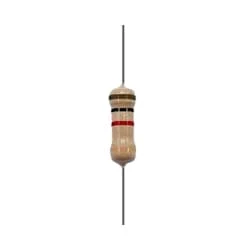
| Fig 3: Resistor |
The main function of a resistor is to block the flow of current or cause a voltage drop in an electronic circuit. In short, the function of the register is to prevent the movement of electricity. When we know about electronics, the first name that comes is Resistor. It is basically a common component of electronics. This component is used in every electronic circuit. A resistor is a very familiar component to those who work with electronics. It has a special function. Resistance is denoted by R. Its unit is the ohm (Ω). The following figure shows some resistor symbols that are used in various circuit boards and circuit diagrams.
03. Diode
 |
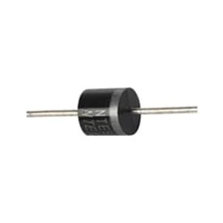
| Fig 4: Diode |
The word diode is a combination of two words, 'die' and 'electrode' so we can generally say that an electronics component having two electrodes is a diode. Diode or rectifier is used in various ways in electronics. However, the main and main function of a diode or rectifier in electronics is to convert AC current into DC current and make the current constant. And this process of converting current AC to DC is called rectification. When current is supplied to the diode, it cannot return because the diode has negative to positive, denoted by P and N. P means anode positive PN means cathode negative.
Thank You for visiting the website. Keep visiting for more Updates.


Post a Comment
Do leave your comments