220V to 12V Converter:
This Diagram shows The Converter is built With CMOS 4047 Which Is The main component of This Small voltage Converter That transforms a 12VDC Into 220VAC. 4047 is used As an Astable multivibrator, Pins 10 And 11 Will have a symmetrical rectangular Signal which is amplified by Two Darlington Transistors And Finally, Reaches The secondary Coil of The Main transformer.
Diagram of 220V to 12V Converter wiring:
Components Need for this Project:
You can get the components from any of the sites below:
- 17V Transformer [See Buy Click Amazon]
- 1000UF (50V) Capacitor [See Buy Click Amazon]
- LM7812 Transistor [See Buy Click Amazon]
- IN4007 Diode [See Buy Click Amazon]
- 1A Fuse [See Buy Click Amazon]
- 1k Resisitor [See Buy Click Amazon]
- DC LED Bulb [See Buy Click Amazon]
*Please note: These are affiliate links. I may make a commission if you buy the components through these links. I would appreciate your support in this way!
Read Also:
Components used to make the 220V to 12V Converter:
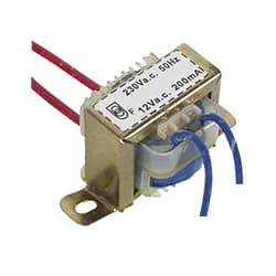
01. 17V Transformer
 |
| Fig 2: 17v Transformer |
This diagram shows Transformer 2 type step-up & step-down. Transformer has 240V primary windings and center-tapped secondary winding. The Electric transformer has flying-colored insulated connecting leads (Approx 100mm long). The Transformer act as a step-down transformer reducing AC - 240V to AC - 6v, 9v, and 12V.
02. 1000UF (50V) Capacitor
 |
| Fig 3: 100UF (50) Capacitor |
A capacitor is basically an electric charge storage device or an electrical passive device that can store charge. Its Bengali meaning is "container" which means that holds an electric charge. And the device made by separating the two plates by placing a non-conductive material (Dielectric) between the two conductive plates is called a capacitor. A capacitor consists of a dielectric material between two conductive layers. A capacitor in a circuit stores electrical energy or charge from a source. Another popular name is a condenser.
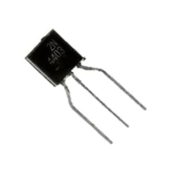
03. LM7812 Transistor
 |
| Fig 4: LM7812 Transistor |
Transistor is a semiconductor device, which is commonly used as an amplifier and electrically controlled switch. Transistors are used as Basic Building Blocks in Computers, Cellular Phones, and all Other Modern Electronics. In terms of the structure of the electronic transistor, the transistor is made by combining two diodes together. For example, if you know that a diode has a p-n junction, adding another p to it will make a p-n-p transistor. It is nothing more than an initial idea. Currently, transistors are not made this way. Transistors are made in a more advanced way.
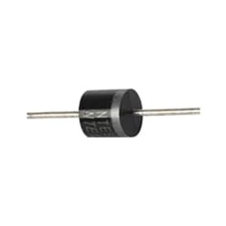
04. IN4007 Diode
 |
| Fig 5: IN4007 Diode |
The word diode is a combination of two words, 'die' and 'electrode' so we can generally say that an electronics component having two electrodes is a diode. Diode or rectifier is used in various ways in electronics. However, the main and main function of a diode or rectifier in electronics is to convert AC current into DC current and make the current constant. And this process of converting current AC to DC is called rectification. When current is supplied to the diode, it cannot return because the diode has negative to positive, denoted by P and N. P means anode positive RN means cathode negative.
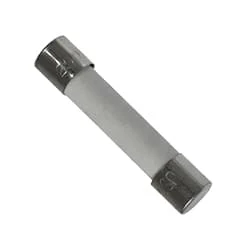
05. 1A Fuse
 |
| Fig 6: 1A Fuse |
A fuse is an electrical, electronic, or mechanical device that protects a circuit from excessive current or overload. The metal of the fuse is made or designed in such a way that it can carry a very small amount of current. When short-circuited or overloaded, the high-flow current generates thermal heat that melts the fuse's metal or element and creates a gap. This gap interrupts the flow of current in the fuse. Basically, this is how a fuse works. If the fuse is once blown or damaged it needs to be replaced to allow current to flow again in the circuit.
06. 1k Resisitor
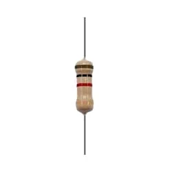 |
| Fig 7: 1k Resisitor |
The main function of a resistor is to block the flow of current or cause a voltage drop in an electronic circuit. In short, the function of the register is to prevent the movement of electricity. When we know about electronics, the first name that comes is Resistor. It is basically a common component of electronics. This component is used in every electronic circuit. A resistor is a very familiar component to those who work with electronics. It has a special function. Resistance is denoted by R. Its unit is the ohm (Ω). The following figure shows some resistor symbols that are used in various circuit boards and circuit diagrams.
07. DC LED Bulb
 |
| Fig 8: DC LED Buld |
LED (light emitting diode) is basically a type of diode that emits light at a certain voltage. These LED bulbs turn on at a very low voltage such as 2~3 volts. When the light emitting diode is forward biased, the free electrons in the n-type semiconductor gain electrical energy from the DC source and move from the balance band to the conduction band and the electrical Under the influence of pressure, current flows through the junction to P-type. In the p-type majority of carrier holes are located in the valence band. Thus basically the p-n junction becomes a light source.
Thank You for visiting the website. Keep visiting for more Updates.


Post a Comment
Do leave your comments