Table Fan Speed Controller Wiring | Electric fan speed controller
Table Fan Speed Controller Wiring:
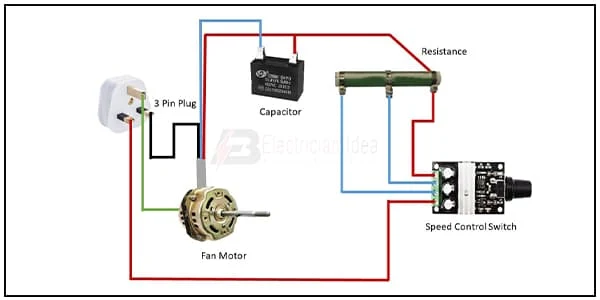
This circuit diagram shows how to connect the table fan speed controller wiring. In this circuit diagram, we use a 3-Pin plug, a capacitor, a fan motor, a resistance, speed controller switch. This circuit is very simple and easy to connect. If you want to make this circuit please follow our youtube video at below the article.
Diagram of Fan speed controller wiring:
 |
| Fig 1: Table Fan Speed Controller wiring |
Components Need for this Project:
You can get the components from any of the sites below:
- 3-Pin Plug [See Buy Click Amazon]
- Capacitor [See Buy Click Amazon]
- Fan Regulator [See Buy Click Amazon]
- Dump Load Resistor [See Buy Click Amazon]
*Please note: These are affiliate links. I may make a commission if you buy the components through these links. I would appreciate your support in this way!
$ads={1}Read Also:
Components used to make the Table Fan Speed Controller:
01. 3-Pin Plug
 |
| Fig 2: 3-Pin Plug |
Many of us mistake a device that receives power through a 3-pin plug as a 3-phase load. Actually, they are single-phase loads and a 3-pin plug is used in these devices to avoid electrical accidents. This type of plug has three pins called 'Live', 'Neutral', and 'Earthing' which are marked by letters 'L', 'N', and 'E' respectively. The three wires to which these three pins are connected are also colored differently. The earth pin is connected to yellow or green, live pin to red or brown and neutral pin to black or blue wire. Among these pins, the earth pin is the longest and thickest.
02. Capacitor
 |
| Fig 3: Capacitor |
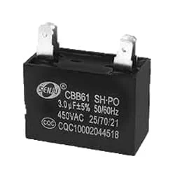
A capacitor is basically an electric charge storage device or an electrical passive device that can store charge. Its Bengali meaning is "container" which means that holds an electric charge. And the device made by separating the two plates by placing a non-conductive material (Dielectric) between the two conductive plates is called a capacitor. A capacitor consists of a dielectric material between two conductive layers. A capacitor in a circuit stores electrical energy or charge from a source. Another popular name is a condenser.
03. Fan Regulator
 |
| Fig 4: Fan Regulator |
Reduces fan speed by switching on and off. Reducing the speed of the fan, the power Consumption is also Reduced. It is basically a wire wood resistor-based regulator. The large regulators that were used in the past took up more than half of the switchboard space and were very hot. It looks very small in size. Almost equal to a switch. Electrical regulators are basically made by winding copper wire on an iron core. As Electricity Travels Long Distances Through These Wires, Some of The Electrical Energy is Converted Into Heat Energy.
04. Dump Load Resistor
 |
| Fig 5: Dump Load Resistor |
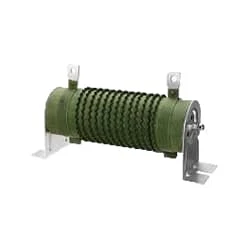
This diverts load resistor is for use to divert the excess power Being Generated When wind Turbine Generator Batteries are full and can be run at 100% duty cycle due to the quality Double wire wound Design. It Can Also be Used With a Solar Array. A dump load for a Wind resistor is a device or system that is used to dissipate excess Energy generated by the turbine when the power Grid is not able to Accept it. The Function of a Resistor is to Block an Electric Current.
Thank You for visiting the website. Keep visiting for more Updates
$ads={2}
Frequently Asked Questions
How do 3-speed fan controllers work?
A three-speed ceiling fan wall switch typically works by controlling the flow of electricity to the fan motor at different levels. The switch has multiple settings, usually labeled as low, medium, or high.
How does a fan speed controller work?
A fan speed controller controls the voltage across the fan or therefore indirectly controls its speed. A fan speed regulator actually measures or regulates the speed of the fan using its tachometer.
How do I slow down my fan speed?
You can add a resistor, a capacitor, and an inductor in series with a fan permanently. This will increase overall impedance or reduce the current, thus reducing the fan speed. Another possibility is to change the capacitor in auxiliary winding from 2.25 mfd to say 1.85 and 2 mfd. This will reduce the fan speed.
How fan speed is controlled by the regulator?
A series of connections implies the resistance is in line with the fan. This reduces the voltage drop across the fan or its speed to your desired level. The greater the resistance, the higher the voltage drop across it, and that lowers the speed of the fan.
Can a capacitor reduce fan speed?
By altering the capacitance, the fan's motor could be made to run at different speeds. When the capacitance is changed, the amount of phase shift in the current flow running through the motor changes, which in turn affects the fan's speed. So, a capacitor could indeed have a significant effect on the speed of a ceiling fan.


Post a Comment
Do leave your comments