Power Factor Improvement Methods 3-Phase PFI:
This diagram shows how to connect Power Factor Improvement Methods 3 Phase PFI. In this circuit diagram, we just try to describe simply how to connect a Power Factor Improvement Methods 3 Phase PFI. This diagram is for Power Factor Improvement Methods 3 Phase PFI Industrial wiring. So you can wire your industrial like this diagram very easily. If you want to learn how to connect this circuit clearly you can follow our youtube video link below.
Diagram of Power Factor Improvement Methods 3-Phase PFI:
Components Need for this Project:
You can get the components from any of the sites below:
- PFI Relay Control [See Buy Click Amazon]
- MCCB [See Buy Click Amazon]
- Capacitor [See Buy Click Amazon]
- Selector Switch [See Buy Click Amazon]
- Fuse [See Buy Click Amazon]
*Please note: These are affiliate links. I may make a commission if you buy the components through these links. I would appreciate your support in this way!
Read Also:
Components used to make the PFI Methods 3 Phase:
01. PFI Relay Control
 |
| Fig 2: PFI Relay Control |
PFI stands for Power Factor Improvement. Reducing the amount of reactive power in a system and increasing the amount of active power. We usually use capacitor bank or synchronous motor or phase advancer to correct and improve the power factor. Power factor correction is done using capacitor bank in industry. We can use capacitors in each load instead of using capacitor banks centrally. Or we can improve the power factor by reducing the load which is responsible for the low power factor.
02. MCCB
 |
| Fig 3: MCCB |
MCCB (Molded Case Circuit Breakers) is a Required Component of Electrical Systems, Providing Overload Protection And Short-Circuit Protection. Circuit breakers are electrical devices that offer protection against fault currents. Molded Case Circuit Breakers (MCCB) or Molded Case Circuit Breakers Use air as The Dielectric Medium to Break a Circuit. Air Has a Low Dielectric Strength as Opposed to Other Mediums Which is why it is Used for Protection in low-Voltage Circuits. In Most Cases, Molded Case Circuit Breakers are installed in the Main Power Distribution Board of a Facility, Allowing the system to be easily shut Down When Necessary.
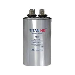
03. Capacitor
 |
| Fig 4: Capacitor |
A Run Capacitor is Used in Single-Phase Motors to Maintain a Running Torque on an Auxiliary Coil While The Motor is Toaded. These Capacitors Are Considered Continuous Duty While The Motor is Powered And Will Remain in The Circuit While The Starts Capacitor Drops out. The Run Capacitor, Also Sometimes Called an “A/C Capacitor,” Uses Its Stored Energy to Turn or Run The fan Motor. Without The Run Capacitor, The Fan Cannot Turn. Run Capacitors Are Also Rated by Voltage Classification. The Voltage Classifications are 370V and 440V.
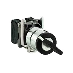
04. Selector Switch
 |
| Fig 5: Selector Switch |
Selector Switches Can be Rotated left, Right, or in The Center in Order to Open or Close The Electrical Contacts. The Function of a Selector Switch is To Control Devices as well as Switch Between a Minimum of Two or More Circuits. The perfect Use For a Selector Switch is When Used for Controlling an Output of a Device. Selector Switches Come as a Complete Unit Often listed as a Terminal Block Meaning the Selector Switch is a Complete Block Which Makes it Simple And easy to Install.
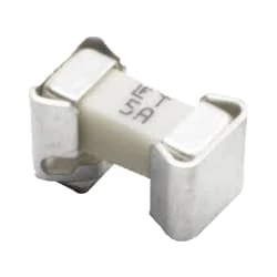
05. Fuse
 |
| Fig 6: Fuse |
Fuses have Been Used as Essential Safety Devices From the Early Days of Electrical Engineering. Today There are Thousands of Different fuse Designs Which have Current Voltage ratings, Breaking Capacity, and Response Times, Depending on the Application. Electricity Component Current Operating Characteristics of Fuses are Chosen to Provide Adequate Protection Without Needless Interruption. House Wiring regulations usually define a Maximum fuse Current rating for Particular Circuits. When a Damaged live Wire Makes contact with a Metal Case that is connected to the Ground. A Short Circuit will Form and The Fuse will Melt.
Thank You for visiting the website. Keep visiting for more Updates


Post a Comment
Do leave your comments