AC Motor Speed Controller Circuit:
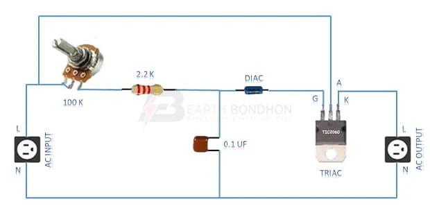
This Diagram Shows ac motor speed controller circuit. This triac-based 220V AC motor speed controller circuit is designed for Controlling the Speed of small Household motors like drill Machines. Flexible Low-Voltage Drives are Designed to Control the Speed of an Electric Motor, save Energy, and Optimize Energy Consumption. Easy Setup and High Performance. Variable Speed Drives With an Integrated PLC. Motor Speed Controllers for Applications that Require Energy Efficiency, Such as Pumping, Ventilating, or Compressing.
Diagram of Motor speed controller wiring:
Components Need for this Project:
You can get the components from any of the sites below:
- 100K Potentiometer [See Buy Click Amazon]
- 2.2K Resistor [See Buy Click Amazon]
- DIAC [See Buy Click Amazon]
- TRIAC [See Buy Click Amazon]
- 0.1uf Ceramic Capacitor [See Buy Click Amazon]
*Please note: These are affiliate links. I may make a commission if you buy the components through these links. I would appreciate your support in this way!
Read Also:
Components used to make the motor speed controller :
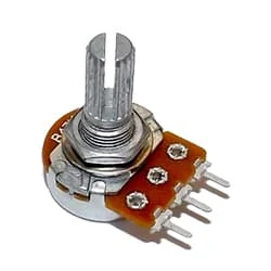
01. 100K Potentiometer
 |
| Fig 2: 100K Potentiometer |
A Variable Resistor is a Type of Resistor Whose Electrical Resistance Value Can be Adjusted On Demand. Variable Resistors are Used in An Electronic Circuit to Adjust Circuit Resistance as a Means to Control The Voltage or Current Within a Circuit. The electrical resistance is Varied by Sliding a Wiper contact Along a Resistance Track. Sometimes the Resistance is Adjusted at a Preset value as Required at the Time of the Circuit Building by Adjusting the Screw Attached to it and Sometimes Resistance can be Adjusted When Required by Controlling The Knob Connected to it.
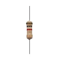
02. 2.2K Resistor
 |
| Fig 3: 2.2K Resistor |
The main function of a resistor is to block the flow of current or cause a voltage drop in an electronic circuit. In short, the function of the register is to prevent the movement of electricity. When we know about electronics, the first name that comes is Resistor. It is basically a common component of electronics. This component is used in every electronic circuit. A resistor is a very familiar component to those who work with electronics. It has a special function. Resistance is denoted by R. Its unit is the ohm (Ω). The following figure shows some resistor symbols that are used in various circuit boards and circuit diagrams.
03. DIAC
 |
| Fig 4: DIAC |
Diode conducts current only after its breaks overvoltage. When a breakdown occurs, the diode enters the negative dynamic resistance region. As a result, the potential drop across the diode decreases and usually the current in the diode increases sharply. Below this value, the diode returns high resistance and is in a non-conducting state. Most discs have a three-layer configuration with a break-over voltage of around 30 volts. The disc has no gate edge, so it is different from other thyristors, which typically use a trigger.
04. TRIAC
 |
| Fig 5: TRIAC |
Triac is a switching semiconductor electronic device with three current gates or terminals The Triac conducts only when its gate is triggered by a positive or negative voltage/pulse. Below are the names of some devices in which Triac is a widely used-Light dimmer. Heat controller of the heater. In the time delay relay circuit. Speed control of the electric fan, and motor.In tap-changing of power transformers.As the switch of high powered lamps.Current regulation of advanced battery chargers through AC control.Current control in arc welding. etc. There are many other uses of trials.
05. 0.1uf Ceramic Capacitor
 |
| Fig 6: 0.1uf Ceramic Capacitor |
A capacitor is basically an electric charge storage device or an electrical passive device that can store charge. Its Bengali meaning is "container" which means that holds an electric charge. And the device made by separating the two plates by placing a non-conductive material (Dielectric) between the two conductive plates is called a capacitor. A capacitor consists of a dielectric material between two conductive layers. A capacitor in a circuit stores electrical energy or charge from a source. Another popular name is a condenser.
Thank You for visiting the website. Keep visiting for more Updates.


Post a Comment
Do leave your comments