Pump Motor Starter Connection:
This circuit diagram shows Pump Motor Starter Connection. In this circuit, we use a TP MCB a DP MCB, a Transformer, 3 phase motor, a float switch, a magnetic contactor, and a relay. Here we need to connect all components very simply like our circuit diagram.
Diagram of Pump Motor wiring:
Components Need for this Project:
You can get the components from any of the sites below:
- TP MCB [See Buy Click Amazon]
- DP MCB [See Buy Click Amazon]
- Transformer [See Buy Click Amazon]
- Relay [See Buy Click Amazon]
- Contactor [See Buy Click Amazon]
- Float Switch [See Buy Click Amazon]
- 3 Phase Motor [See Buy Click Amazon]
Read Also:
Components used to make the Pump Motor starter diagram:
01. TP MCB
 |
| Fig 2: TP MCB |
Three wires can be controlled by a triple pole MCB. Triple pole MCB circuit breakers are generally used in three-phase lines. A triple-pole MCB circuit breaker has three wires at its input and three wires at its output. But one can use this circuit breaker in a single-phase line. TP MCB widely used in industries. The reason is that it has three poles. And this TP circuit breaker is used to provide three-phase and three-phase connections. A neutral is not normally used in three-phase lines. But a 4-pole MCB circuit breaker is used if needed.
02. DP MCB
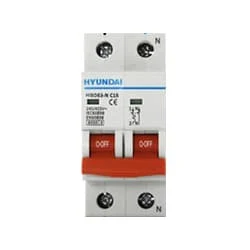 |
| Fig 3: DP MCB |
Double pole MCB can control two wires. This circuit breaker is generally used in single-phase electric lines. Double pole MCB circuit breaker input has two wires supply two wires and an output. In a single-phase line, A double-pole MCB circuit breaker is used to give good production. This circuit breaker is provided through phase and neutral circuit breaker, it is very safe. This circuit breaker is preferred for home appliances. A DP MCB usually trips for 2 reasons 1. Overload 2. Short circuit.
03. Transformer
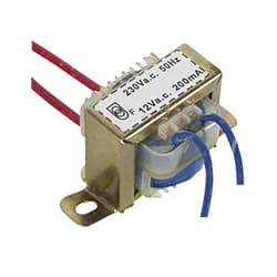 |
| Fig 4: Transformer |
Electricity can be transferred from one AC circuit to another using a transformer. The electromagnetic induction concept is used by a transformer to either step-up or step-down the AC voltage. Transformers are widely used to reduce the power in the circuits of low-voltage devices like doorbells. This diagram shows Transformer 2 type step-up & step-down. Transformer has 240V primary windings and center-tapped secondary winding. The Electric transformer has flying-colored insulated connecting leads (Approx 100mm long). The Transformer act as a step-down transformer reducing AC - 240V to AC - 6v, 9v, and 12V.
04. Relay
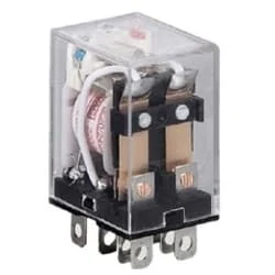 |
| Fig 5: Relay |
This relay is known as 8 pin relay because it has 8 terminals. When coil power is supplied. A magnetic induction is created due to which the connected sheet of the Com part moves towards the NO part changing to NO-NC. The former NC region loses conductivity and becomes NO. Thus, as long as power is supplied to the coil, the NO and NC positions will remain in the alternating state, and when the power is removed from the coil, it will return to its original position. This is basically how a relay switch works.
05. Contactor
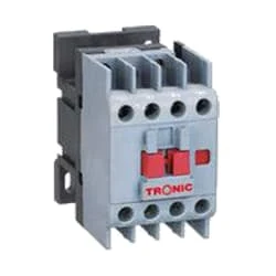 |
| Fig 6: Contactor |
A magnetic contactor is an electrical device used for load control, automation, and protection. It is much like a magnetic reel. However, relays are generally used for low power and voltage, on the other hand, when we think of high power, these heavy-duty contractors only come to mind. It basically works by switching the load on and off. It has 3 terminals whose inputs are denoted as L1, L2, L3, and outputs as T1, T2, and T3. The circuit of the load is made in automation mode or protection using auxiliary contacts. It has two types of terminals. 1) Normally Open (NO). 2) Normally Closed (NC)
06. Float Switch
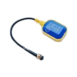 |
| Fig 7: Float Switch |
Float switch The water tank can basically be controlled with this switch. It basically works like a switch. This float switch has a magnetic reed sensor. Float Switch It is a water level controller. With this, you can create interesting projects. The Float Switch is Behind the Panel at The Bottom of the Dishwasher door, directly under the float. With this float switch, you can control the water tank motor/pump motor of your house in which water is raised in the tank.
07. 3 Phase Motor
 |
| Fig 8: 3 Phase Motor |
A Three-Phase Motor is an Electric Motor That Typically Receives its Power From a Three-Phase System (three-phase current) This can be realized via a Three-Phase Mains Supply or a Frequency Inverter. Three-Phase Motors are Available as Synchronous and Asynchronous Motors. Three Phase Alternating Current Power Motor is Economical to Supply Power to the data Center Since it Requires Less Conductor Material to Supply Electricity. This Explains Why 3 Phase Alternating Current Motor is Used in Electric Transmission, Generation, and Distribution in Most Countries Worldwide.
Thank You for visiting the website. Keep visiting for more Updates.


Post a Comment
Do leave your comments