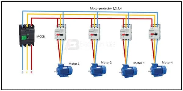
Motor Control Center Panel Wiring:
This diagram shows how to make Motor Control Center Panel Wiring. In this circuit, we use an MCCB ( Molded Case Circuit Breaker ), four MPCB ( Motor Protector Circuit Breaker ), and four 3-phase motors. First, we need to connect MCCB, then connect all MPCBs and all Motors with this circuit. Now it's ready to use.
Diagram of Motor control wiring:
Components Need for this Project:
You can get the components from any of the sites below:
- MCCB [See Buy Click Amazon]
- Motor Starter Protector [See Buy Click Amazon]
- 3 Phase Motor [See Buy Click Amazon]
Read Also:
Components used to make the Motor control center diagram:
01. MCCB
 |
| Fig 2: MCCB |
MCCB (Molded Case Circuit Breakers) is a Required Component of Electrical Systems, Providing Overload Protection And Short-Circuit Protection. Circuit breakers are electrical devices that offer protection against fault currents. Molded Case Circuit Breakers (MCCB) or Molded Case Circuit Breakers Use air as The Dielectric Medium to Break a Circuit. Air Has a Low Dielectric Strength as Opposed to Other Mediums Which is why it is Used for Protection in low-Voltage Circuits. In Most Cases, Molded Case Circuit Breakers are installed in the Main Power Distribution Board of a Facility, Allowing the system to be easily shut Down When Necessary.
02. Motor Starter Protector
 |
| Fig 3: Motor Starter Protector |
3-phase Motor starters, motor protection circuit breakers (MPCBs) or manual motor protectors (MMPs) control wiring useing switching. There are electromechanical protection devices for the main circuit diagram. They are mainly used to switch motors ON/OFF manually and to provide fuseless protection against short-circuit overload and phase failures switching motor control circuit diagram.
03. 3 Phase Motor
 |
| Fig 4: 3 Phase Motor |
A Three-Phase Motor is an Electric Motor That Typically Receives its Power From a Three-Phase System (three-phase current) This can be realized via a Three-Phase Mains Supply or a Frequency Inverter. Three-Phase Motors are Available as Synchronous and Asynchronous Motors. Three Phase Alternating Current Power Motor is Economical to Supply Power to the data Center Since it Requires Less Conductor Material to Supply Electricity. This Explains Why 3 Phase Alternating Current Motor is Used in Electric Transmission, Generation, and Distribution in Most Countries Worldwide.
Thank You for visiting the website. Keep visiting for more Updates.


Post a Comment
Do leave your comments