Photocell Connection Wiring:
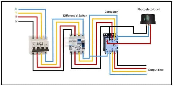
This diagram shows how to make Photo Control Cell Connection Wiring. In this circuit, we use FP MCB ( Four Pole Miniature Circuit Breaker ), a DIfferential Switch, a photocell sensor, and a magnetic contactor. First, we need to connect TP MCB with the power source. then connect all components with the circuit. Now this circuit is ready to use.
Diagram of Photocell wiring:
Components Need for this Project:
You can get the components from any of the sites below:
- FT MCB [See Buy Click Amazon]
- RCCB [See Buy Click Amazon]
- Contactor [See Buy Click Amazon]
- Photocell [See Buy Click Amazon]
Read Also:
Components used to make the photocell diagram:
01. FT MCB
 |
| Fig 2: FT MCB |
Four pole MCCB for Four wires connections, the one additional Four pole for neutral wire connection so that between neutral and any of the other three will supply. It is used where is the possibility of a high neutral current (due to unbalanced loads and /or Third and multiple Third harmonics current etc) and Neutral / Earth Protection is provided on Neutral. Four Pole Circuit Breakers Have advantages in the case When one of the Poles of the Device will get Damaged, and they also provide Isolation from neutral voltage.
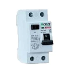
02. RCCB
 |
| Fig 3: RCCB |
The RCCB (Residual Current Circuit Breaker) or RCCB is an electrical protective device. A residual Current Circuit Breaker is specially designed to protect the electrical circuit against earth faults and humans from electrical shock. In this, under normal conditions the load is always connected between the phase terminal to the neutral terminal, hence the flow of the phase current is equal to the neutral current. Earth fault or fault in a power system can cause excess heating, more power consumption, burning or fire, etc. So, protection against earth leakage is very important.
03. Contactor
 |
| Fig 4: Contactor |
A magnetic contactor is an electrical device used for load control, automation, and protection. It is much like a magnetic reel. However, relays are generally used for low power and voltage, on the other hand, when we think of high power, these heavy-duty contractors only come to mind. It basically works by switching the load on and off. It has 3 terminals whose inputs are denoted as L1, L2, L3, and outputs as T1, T2, and T3. The circuit of the load is made in automation mode or protection using auxiliary contacts. It has two types of terminals. 1) Normally Open (NO). 2) Normally Closed (NC)
04. Photocell
 |
| Fig 5: Photocell |
An Automatic Day Night Light Sensor Switch can Switch on Any Electrical Device Automatically When Dark Falls And Switch off in the Morning Automatically. This Night light With an Energy-Efficient LED (Light Emitting Diode) can be Plugged into the Socket and has a light sensor so that the lamp switches on automatically when it gets dark. This is a Photo Technology-Based automatic sensor switch for 220V AC mains, which can be Widely Used in Street Lights, Factories, Gardens, Shops, Etc., and Other Places for Automatic Lighting. Turns ON the Light in the Dark & Turns OFF in The Light.
Thank You for visiting the website. Keep visiting for more Updates.


Post a Comment
Do leave your comments