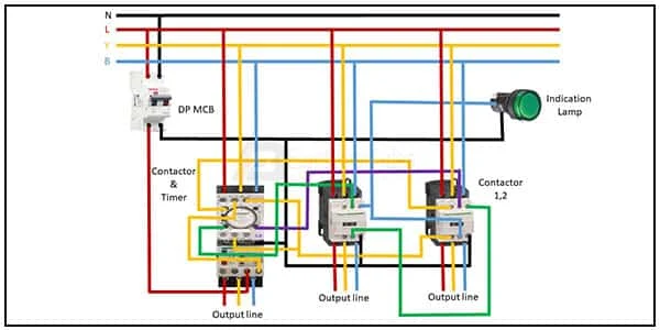
3 Phase star motor connection diagram:
This diagram shows how to make 3 phase star motor connection diagram. In this circuit, we use a DP MCB ( Double Pole Minature Circuit Breaker ), three magnetic contactors and an overload, and an indicator lamp. First, we need to connect DP MCB with the power source, then connect all component like our diagram.
Diagram of 3 Phase star motor wiring:
Components Need for this Project:
You can get the components from any of the sites below:
- DP MCB [See Buy Click Amazon]
- Contactor [See Buy Click Amazon]
- Overload [See Buy Click Amazon]
- Indicator Lamp [See Buy Click Amazon]
Read Also:
Components used to make the 3 Phase motor wiring:
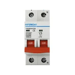
01. DP MCB
 |
| Fig 2: DP MCB |
Double pole MCB can control two wires. This circuit breaker is generally used in single-phase electric lines. Double pole MCB circuit breaker input has two wires supply two wires and an output. In a single-phase line, A double-pole MCB circuit breaker is used to give good production. This circuit breaker is provided through phase and neutral circuit breaker, it is very safe. This circuit breaker is preferred for home appliances. A DP MCB usually trips for 2 reasons 1. Overload 2. Short circuit.
02. Contactor
 |
| Fig 3: Contactor |
A magnetic contactor is an electrical device used for load control, automation, and protection. It is much like a magnetic reel. However, relays are generally used for low power and voltage, on the other hand, when we think of high power, these heavy-duty contractors only come to mind. It basically works by switching the load on and off. It has 3 terminals whose inputs are denoted as L1, L2, L3, and outputs as T1, T2, and T3. The circuit of the load is made in automation mode or protection using auxiliary contacts. It has two types of terminals. 1) Normally Open (NO). 2) Normally Closed (NC)
03. Overload
 |
| Fig 4: Overload |
Overload relays are often used to protect the motor from excessive current flow. Overload relays are used to protect the motor from overheating. Besides some specific faults such as phase to phase, phase to ground, etc. overload relay provides protection to the motor. A thermal overload relay works on the principle of bimetallic strip electro-thermal characteristics. When the bimetallic heats up, the trip function in the overload relay turns on and disconnects the power supply to the contactor coil, thus tripping the overload relay and breaking the motor current and saving the motor.
04. Indicator Lamp
 |
| Fig 5: Indicator Lamp |
An electric current Flow Indicator Senses The electrical Current Through an electrical device And produces visible feedback to Indicate Proper Operation. The Current Flow Indicator Has Voltage And Current Regulation Craving First And Second Inputs Connected To The First And Second Conductors, Respectively. This Publication Provides updated Statistics on a Comprehensive Set of social, Economic, Financial, and Environmental Measures as Well as Select Indicators for Sustainable Development Goals.
Thank You for visiting the website. Keep visiting for more Updates.


Post a Comment
Do leave your comments