Single Phase ampere meter connection:
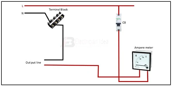
This diagram shows how to make Single phase ampere meter connection. Amp meter Installation. In this circuit, we use a terminal block, SP MCB ( Single Pole Miniature Circuit Breaker ), and an Amper Meter. First, we need to connect the SP MCB with the phase connection, then connect the ampere meter with the phase connection. Then connect the neutral wire with the terminal block. Now this circuit is ready for use. If you want to know more about this circuit please check our youtube video below the post.
Diagram of ampere meter wiring:
Components Need for this Project:
You can get the components from any of the sites below:
- Ampere Meter [See Buy Click Amazon]
- SP MCB [See Buy Click Amazon]
- Terminal Block [See Buy Click Amazon]
Read Also:
Components used to make the single phase ampere meter wiring:
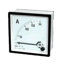
01. Ampere Meter
 |
| Fig 2: Ampere Meter |
The Ammeter (Abbreviation of Ampere Meter) is a Measuring Instrument used to find the Strength of the Current Flowing Around an Electrical Circuit when Connected in Series with the part of the Circuit Being Measured. For Direct Measurement, The Ammeter is Connected in Series With the Circuit in Which The Current is to be Measured. An Ammeter’s Current Sensitivity is Determined by the Amount of Electric Current Required by the coil of the Meter to Produce the Required FSD Movement of the Pointer.
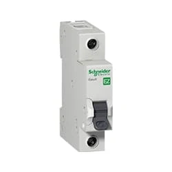
02. SP MCB
 |
| Fig 3: SP MCB |
MCB SP means single pole it protects only one phase switching. MCB (Miniature Circuit Breaker) Curswitch is the most basic general-purpose switch that you use to control a light or another device from one location. These Switches Have Two Brass-Colored Screw Terminals Connected to the hot Power Source Wires. (MCB) For any Distribution Board, the Protection System Must be Used in The Incomer. Phase and Neutral Single Phase Supply to break. 120-volt circuits, 15-20 amp single pole breaker is typically used.
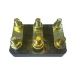
03. Terminal Block
 |
| Fig 4: Terminal Block |
A Terminal Block Consists of Modular Housing With An Insulated Body That Secures Two Or More Wires Together. Terminal Blocks—Also Referred to as terminal Connectors, Connection Terminals, or Screw Terminals—are Used in a Wide Array of Applications Where Electrical Systems Need to be Safely Connected. Electrical Terminals are a Class of Electrical Connectors That are Used to Transfer Electrical Current From a Power or Grounding Source to use. Terminals "Terminate" by Crimping or Soldering to Wire or Cable.
Thank You for visiting the website. Keep visiting for more Updates.
Frequently Asked Questions
An ammeter will be always connected in series because it has a low resistance and the Voltmeter will be always connected in parallel because it has a high resistance. On interchanging their position Circuit diagram, An ammeter is usually connected to a parallel power supply.
Ammeters are connected in series with whatever device's current is to be measured. A series connection is used because objects in a series have the same current passing through them. (See Figure 3, where the Power supply ammeter is represented by the power supply symbol A.)
To measure the total current, the ammeter must be placed at position 1, as all the current in the circuit must pass through this wire, and the ammeters are always connected in series. To measure the total voltage in the circuit, the voltmeter could be placed at either position 3 or position 4.
An Ammeter is used to measure the power supply current flowing through a component/circuit diagram. Since the current remains the same in a series connection and also the resistance of an ammeter is very small it doesn't affect the current to be measured. So, as an ammeter is connected in series to measure the current Circuit diagram.
Digital ammeter designs use a shunt resistor to produce a calibrated voltage Circuit diagram proportional to the current flowing. This voltage is then measured by a digital voltmeter, through the use of an analog-to-digital converter (ADC); the digital display is calibrated to display the current through the shunt.


Post a Comment
Do leave your comments