Fan in Regulator wiring diagram:
This Diagram shows how to make Fan in Regulator Wiring Diagram. Connection of fan regulator. In this circuit, we use an SP MCB ( Single Pole Miniature Circuit Breaker ), an ELCB, a fan regulator, and a ceiling fan. First, we need to connect SP MCB and ELCB with a power source, then connect the regulator and ceiling fan with the power source. Now this circuit is ready for use. This circuit is very simple and easy to make. If you want to know more about this circuit please stay with our website and check our youtube video below the post.
Diagram of fan regulator wiring:
Components Need for this Project:
You can get the components from any of the sites below:
- Fan [See Buy Click Amazon]
- Regulator [See Buy Click Amazon]
- ELCB [See Buy Click Amazon]
- SP MCB [See Buy Click Amazon]
Read Also:
Components used to make the fan regulator wiring:
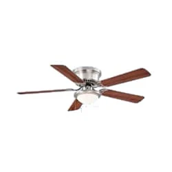
01. Fan
 |
| Fig 2: Fan |
The main driving force behind all ceiling fan systems is the motor used inside the fan. We can also compare it with the soul of a fan. This motor converts the supplied electrical energy into mechanical energy which turns the ceiling fan and gives us air. When current is supplied, the magnetic field formed on the positive half-cycle becomes the reverse magnetic field on the next negative half-cycle. The magnitude part does not rotate and the capacitor is converted to a phase when it is connected to a phase motor or ceiling fan with a helical coil or stationing coil. When power is supplied there is a magnetic difference between the phase currents and the coils (acting as two phases) so that the motor or fan rotates.
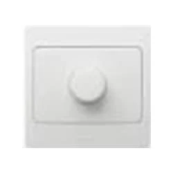
02. Regulator
 |
| Fig 3: Regulator |
Reduces fan speed by switching on and off. Reducing the speed of the fan, the power Consumption is also Reduced. It is basically a wire wood resistor-based regulator. The large regulators that were used in the past took up more than half of the switchboard space and were very hot. It looks very small in size. Almost equal to a switch. Electrical regulators are basically made by winding copper wire on an iron core. As Electricity Travels Long Distances Through These Wires, Some of The Electrical Energy is Converted Into Heat Energy.
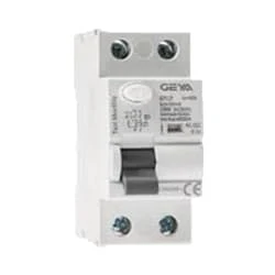
03. ELCB
 |
| Fig 4: ELCB |
An earth-leakage circuit breaker (ELCB) is a safety device used in electrical installations with high Earth impedance to prevent shock.Generally, the current sensing devices termed Residual current Circuit Breaker (RCCB), and voltage detecting devices named Earth Leakage Circuit breaker Earth-Leakage Circuit Breaker (ELCB). For several years, both the voltage and current operated ELCBs were both referred to as ELCB (Earth-Leakage Circuit Breaker) due to their simple name to remember. But the applications of these 2 devices gave growth to the significant mix-up in the electrical industry.
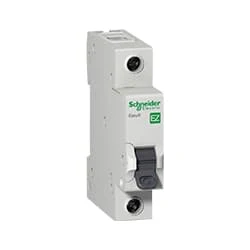
04. SP MCB
 |
| Fig 5: SP MCB |
MCB SP means single pole it protects only one phase switching. MCB (Miniature Circuit Breaker) Curswitch is the most basic general-purpose switch that you use to control a light or another device from one location. These Switches Have Two Brass-Colored Screw Terminals Connected to the hot Power Source Wires. (MCB) For any Distribution Board, the Protection System Must be Used in The Incomer. Phase and Neutral Single Phase Supply to break. 120-volt circuits, 15-20 amp single pole breaker is typically used.
Thank You for visiting the website. Keep visiting for more Updates.
Frequently Asked Questions
They control the voltage across the fan is controlled by a capacitor, the voltage across the Circuit diagram fan determines the fan speed. Capacitive regulators are energy efficient with linear speed control, as quiet operation without humming noises, and highly reliable than electronic type regulators.
When you set the Power supply knob at a particular Project system position, you include a certain resistance in series with the fan. A series connection implies the resistance is in line with the fan Circuit diagram. This reduces the voltage drop across the Power supply fan and its speed to your desired level.
The black wire is used for the power supply ceiling fan. The white wire is neutral, the green wire indicates earthing wire, and the red wire indicates the conductor to carry power to the light fit.
A Fan Regulator, as the name suggests, regulates or controls the Circuit diagram speed of the fan motor. Before dealing with the fan regulator, a brief discussion about the power supply fan motor is necessary, as the main purpose of the regulator is to control the current speed of the fan motor.
The fan regulator is a circular knob on the switchboard that is used to Circuit diagram control or regulate the speed of a ceiling fan. However, the current technology has remote-controlled ceiling fans to offer. These are operated by a remote control thanks to an automated system.


Post a Comment
Do leave your comments