Ampere Meter in voltmeter wiring:
This Diagram shows how to make an Ampere meter in voltmeter wiring. Wiring Voltmeter and amp Meter. In this circuit, we use a DP MCB ( Double Pole Miniature Circuit Breaker ), a voltmeter, an amperemeter, a digital panel meter, a pump controller, and a single-phase pump motor. This circuit is very simple and easy to make. If you want to know more about this circuit please stay with our website and check our youtube video below the post.
Diagram of ampere & voltmeter wiring:
Components Need for this Project:
You can get the components from any of the sites below:
- Pump Contol Box [See Buy Click Amazon]
- Pump Motor [See Buy Click Amazon]
- DP MCB [See Buy Click Amazon]
- Voltmeter [See Buy Click Amazon]
- Amperemeter [See Buy Click Amazon]
- Digital Panel Meter [See Buy Click Amazon]
Read Also:
Components used to make the voltmeter & ampere wiring:
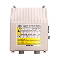
01. Pump Contol Box
 |
| Fig 2: Pump Contol Box |
02. Pump Motor
 |
| Fig 3: Pump Motor |
Single-Phase Induction Motor is Very Simple in Construction, Economical, Reliable, and Easy to Repair And Maintain. Due to all these advantages, it is widely used in vacuum cleaners, fans, centrifugal pumps, blowers, washing machines, etc. It can run only by supplying 1 phase current through this motor. The main two parts of this motor are Rotor and Stator. Among them, the rotating part is the Rotor and the stationary part is the Stator. Like all induction motors, a single-phase induction motor consists of two main parts, the stator, and the rotor.
03. DP MCB
 |
| Fig 4: DP MCB |
Double pole MCB can control two wires. This circuit breaker is generally used in single-phase electric lines. Double pole MCB circuit breaker input has two wires supply two wires and an output. In a single-phase line, A double-pole MCB circuit breaker is used to give good production. This circuit breaker is provided through phase and neutral circuit breaker, it is very safe. This circuit breaker is preferred for home appliances. A DP MCB usually trips for 2 reasons 1. Overload 2. Short circuit.
04. Voltmeter
 |
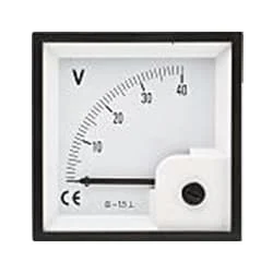
| Fig 5: Voltmeter |
An instrument that measures the potential difference between any two points in a circuit directly in volts is called a voltmeter. To Measure the Potential Difference Between two Points in the Circuit, the Voltmeter Should be Connected in Parallel with those two points. The working common volt meter and ammeter are similar and work on the same principle. Current flows through the coil of the voltmeter at a rate proportional to the voltage and the reading are obtained. The internal resistance of this meter is very high. The coil of a volt meter is made up of many strands of thin wire.
05. Amperemeter
 |
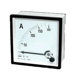
| Fig 6: Amperemeter |
The Ammeter (Abbreviation of Ampere Meter) is a Measuring Instrument used to find the Strength of the Current Flowing Around an Electrical Circuit when Connected in Series with the part of the Circuit Being Measured. For Direct Measurement, The Ammeter is Connected in Series With the Circuit in Which The Current is to be Measured. An Ammeter’s Current Sensitivity is Determined by the Amount of Electric Current Required by the coil of the Meter to Produce the Required FSD Movement of the Pointer.
06. Digital Panel Meter
 |
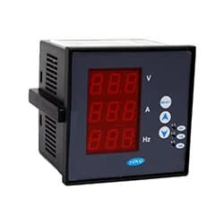
| Fig 7: Digital Panel Meter |
A voltmeter is used to measure voltage. With the load, it is connected in parallel. Common voltmeters and ammeters have similar designs and work in the same ways. A reading is acquired when current through the voltmeter coil is flowing at a rate proportional to the voltage. This meter has a very high internal resistance. A volt meter's coil is constructed of several thin wire strands.
Thank You for visiting the website. Keep visiting for more Updates.
Frequently Asked Questions
Both of these devices are used in electric circuits diagrams but the major difference between a voltmeter and an ammeter is ammeter comes in handy for measuring the flow of current flow whereas the voltmeter comes in handy for measuring the voltage or emf across 2 points in an electric circuit diagram.
An ammeter is used to measure the magnitude of the current flow. It is also called an ampere meter because an ampere is the unit of current flow. It is a device used to determine the magnitude of current flowing in a circuit diagram.
An ammeter (abbreviation of Ampere meter) is an instrument used to measure the current flowing a circuit diagram. Electric current flow is measured in amperes (A), hence the name. For direct measurement, the ammeter is connected in series with the circuit diagram in which the current flow is to be measured.
To measure the current flowing through a circuit diagram using an ammeter, you need to connect the ammeter in series with the circuit diagram. This means that the ammeter is connected in line with the components through which the current flow is to be measured.
Every ammeter comes with red and black wires that connect the device to an electrical circuit diagram. The probe end of each wire is what connects to the circuit diagram. The opposite end plugs into a slot on the multimeter, which is always the COM port for the black wire.


Post a Comment
Do leave your comments