Double Relay Diagram:
This diagram shows how to make Dual Relay Wiring Diagram. In this circuit, we use two SP MCBs ( Single Pole Miniature Circuit Breaker), and two 8-pin relays. First, we need to connect the SP MCBs with a power source, then connect them with two relays like in our diagram. This circuit is ready for use. If you want to know more about this circuit please stay with our youtube video below the post.
Diagram of Relay wiring:
Components Need for this Project:
You can get the components from any of the sites below:
Read Also:
Components used to make the Relay diagram:
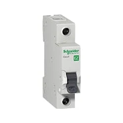
01. SP MCB
 |
| Fig 1: SP MCB |
MCB SP means single pole it protects only one phase switching. MCB (Miniature Circuit Breaker) Curswitch is the most basic general-purpose switch that you use to control a light or another device from one location. These Switches Have Two Brass-Colored Screw Terminals Connected to the hot Power Source Wires. (MCB) For any Distribution Board, the Protection System Must be Used in The Incomer. Phase and Neutral Single Phase Supply to break. 120-volt circuits, 15-20 amp single pole breaker is typically used.
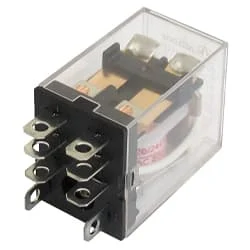
02. Relay
 |
| Fig 3: Relay |
This relay is known as 8 pin relay because it has 8 terminals. When coil power is supplied. A magnetic induction is created due to which the connected sheet of the Com part moves towards the NO part changing to NO-NC. The former NC region loses conductivity and becomes NO. Thus, as long as power is supplied to the coil, the NO and NC positions will remain in the alternating state, and when the power is removed from the coil, it will return to its original position. This is basically how a relay switch works.
Thank You for visiting the website. Keep visiting for more Updates.
Frequently Asked Questions
A single-pole double-throw (SPDT) relay has 1 pole and 2 throws. Based on the Circuit diagram default position of the pole, one throw is considered normally open (NO) while the power supply other is normally closed (NC).
DPDT stands for double-pole and double-throw relay which is an electromagnetic project system device used to separate two circuits electrically and connect them and magnetically. They are often used to interface an electronic circuit diagram, which works at a low voltage to an electrical circuit diagram which works at a high voltage.
A Double Pole (or DP) switch is a switch that controls 2 circuit diagrams at the same time. In terms of residential switching, this normally means it switches the live and neutral at the power supply same time.
A double pole switch would have one hot wire in and two hot wires out, basically the same as a 3-way switch. On a 3-way switch, the side with two wires is called Traveler Wires, and one of those wires is always hot, depending upon whether the switch is up or down.
A Double Pole power supply switch (also known as a DP switch) is a switch that switches both electrical circuit diagrams (live and neutral) at the same time. This leaves the Load, where the appliance is connected, completely isolated.


Post a Comment
Do leave your comments