Automatic Timer relay Using Alarm:
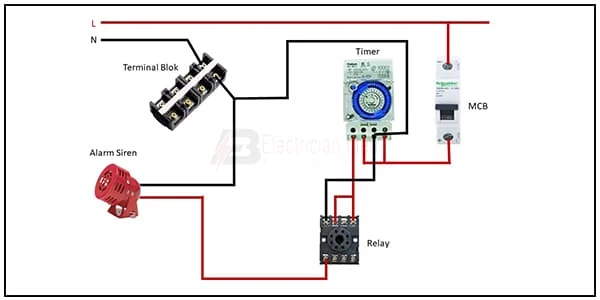
This diagram shows how to make Automatic Timer relay Using an Alarm. In this circuit, we use a terminal block, an 8-pin timer relay, an SP MCB( Single Phase Miniature Circuit Breaker), an alarm siren, and a relay. First, we need to connect the SP MCB, then connect the timer and relay with phase connection, then connect the alarm siren. Now this circuit is ready for use. If you want to know more about this circuit please check our youtube video below the post.
Diagram of Timer relay using Alarm wiring:
Components Need for this Project:
You can get the components from any of the sites below:
- SP MCB [See Buy Click Amazon]
- Timer [See Buy Click Amazon]
- 8-pin relay [See Buy Click Amazon]
- Alarm Siren [See Buy Click Amazon]
- Terminal Block [See Buy Click Amazon]
Read Also:
Components used to make the timer alarm:
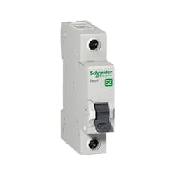
01. SP MCB
 |
| Fig 2: SP MCB |
MCB SP means single pole it protects only one phase switching. MCB (Miniature Circuit Breaker) Curswitch is the most basic general-purpose switch that you use to control a light or another device from one location. These Switches Have Two Brass-Colored Screw Terminals Connected to the hot Power Source Wires. (MCB) For any Distribution Board, the Protection System Must be Used in The Incomer. Phase and Neutral Single Phase Supply to break. 120-volt circuits, 15-20 amp single pole breaker is typically used.
02. Timer
 |
| Fig 3: Timer |
Timer is a specialized type of clock used for measuring specific time intervals.An electromechanical cam timer uses a small synchronous AC motor turning a cam against a comb of switch contacts. This type of timer often has a friction clutch between the gear train and the cam, the cam can be turned to reset the time.A simple example of the first type is an hourglass. Working method timers have two main groups: hardware and software timers.Most timers give an indication that the time interval that had been set has expired.
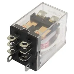
03. 8-pin relay
 |
| Fig 4: 8-pin Timer |
This relay is known as 8 pin relay because it has 8 terminals. When coil power is supplied. A magnetic induction is created due to which the connected sheet of the Com part moves towards the NO part changing to NO-NC. The former NC region loses conductivity and becomes NO. Thus, as long as power is supplied to the coil, the NO and NC positions will remain in the alternating state, and when the power is removed from the coil, it will return to its original position. This is basically how a relay switch works.
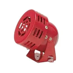
04. Alarm Siren
 |
| Fig 5: Alarm Siren |
An Alarm Siren is a Loud Noise-Making Device. Civil Defense Alarm Sirens are Mounted in Fixed Locations and Used to Warn of Natural Disasters or Attacks. Alarm Sirens are Used on Emergency Service Vehicles such as Ambulances, Police cars, and Fire Engines. There are two General Types: Mechanical and Electronic. A Civil Defense Siren, also known as an Air-Raid Siren or Tornado Siren, is a Siren Used to Provide an Emergency Population Warning to the General Population of Approaching Danger.
05. Terminal Block
 |
| Fig 6: Terminal Block |
A Terminal Block Consists of Modular Housing With An Insulated Body That Secures Two Or More Wires Together. Terminal Blocks—Also Referred to as terminal Connectors, Connection Terminals, or Screw Terminals—are Used in a Wide Array of Applications Where Electrical Systems Need to be Safely Connected. Electrical Terminals are a Class of Electrical Connectors That are Used to Transfer Electrical Current From a Power or Grounding Source to use. Terminals "Terminate" by Crimping or Soldering to Wire or Cable.
Thank You for visiting the website. Keep visiting for more Updates.
Frequently Asked Questions
Electromagnetism is the timer relay working principle. One relay coil is always on, while the other could be turned off and on with an electric signal sent through it from the control device such as a phone or computer system. The “on” coil receives a power supply all the time, making it ready to activate at a moment's notice.
On- or off-delay timers represent the most typical time delay relay for the timers in use. Other types of the include interval-on-operate, flasher, and repeat cycle timers. Normally open and on-delay timers start timing when the input voltage (power supply) is applied. The output is energized at the end of the delay.
Timing relays were similar to other relays in that they too use a coil to control the operation of the contacts. The primary difference between the control relay and a timing relay was that the contacts of the timing relay delayed changing their position when the coil was energized and de-energized.
When a voltage is applied to terminal 15 (the timer trigger) the relay will switch the power supply to the output (terminal 87). As soon as the voltage is removed from terminal 15 the timer will start and power will continue to be fed to terminal 87 for a user-settable period before the relay switches off.
Time delay relays could control activation sequences, ensuring that each stage of the system operates as intended. For example, in a manufacturing process, it may be necessary to activate 1 relay to start a machine before activating another relay for the release of raw materials.


Post a Comment
Do leave your comments