Ceiling Fan Wiring Diagram:
This diagram shows how to make a Ceiling Fan Wiring Diagram. In this circuit, we use a ceiling fan and a switch. First, we need to connect the switch, with the phase connection, then connect the fan with the switch connection. And lastly, connect the neutral wire with the fan. Now this circuit is ready for use. If you want to know more about this circuit please check our youtube video below the post.
Diagram of Fan wiring:
Components Need for this Project:
You can get the components from any of the sites below:
Read Also:
Components used to make the Single phase fan wiring:
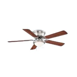
01. Ceiling Fan
 |
| Fig 2: Ceiling Fan |
The main driving force behind all ceiling fan systems is the motor used inside the fan. We can also compare it with the soul of a fan. This motor converts the supplied electrical energy into mechanical energy which turns the ceiling fan and gives us air. When current is supplied, the magnetic field formed on the positive half-cycle becomes the reverse magnetic field on the next negative half-cycle. The magnitude part does not rotate and the capacitor is converted to a phase when it is connected to a phase motor or ceiling fan with a helical coil or stationing coil. When power is supplied there is a magnetic difference between the phase currents and the coils (acting as two phases) so that the motor or fan rotates.
02. Switch
 |
| Fig 2: Switch |
A Single-Pole, Single-Throw (SPST) Switch. It's Got one Output and One Input. The Switch will Either be Closed or Completely Disconnected. SPSTs are Perfect for on-off Switching. They're also a Very Common Form of Momentary Switches. SPST Switches are Commonly Used in a Variety of Electrical Circuits and Applications, Such as Turning on And off Lights, Fans, and Other Appliances. They can Also be Used to Control the Flow of Electricity to Different Parts of a Circuit or to Switch Between Different Circuits Altogether.
Thank You for visiting the website. Keep visiting for more Updates.
Frequently Asked Questions
It looks more complicated, but don't sweat it. The basic idea is that your power supply line is feeding both Circuit diagram switches. Each switch then feeds either the fan (black wire) or the light kit (blue wire). All that's left at this point is to tie together all the project system ground wires and neutral wires (respectively).
In order for the light to be controlled by its own switch, the Circuit diagram wiring between the switch and the fan unit power supply needs a fourth wire, a red wire, to carry the power supply to the light kit.
To install a ceiling fan, you will typically need electrical wires, such as a black (hot) wire, a white (neutral) wire, and a green or bare copper (ground) wire. These wires are used to connect the fan to the electrical system in your home.
If you have two separate switches, one for the light and one for the fan, there should be a 4-wire cable in the ceiling with two hot conductors (black and red), neutral (white), and ground (bare or green insulation). Normally, a fan with light has a black hot lead for the fan and a blue hot lead for the light.
Due to the two different phases in each winding, magnetic rotation is created and thus the rotor starts rotating. Therefore, a capacitor is used in a fan to create a phase difference in the current of the power supply 2 windings which in turn creates a magnetic flux and makes the rotor of the Circuit diagram fan rotate.


Post a Comment
Do leave your comments