Split AC Wiring Connection | indoor to outdoor wiring
Split AC Wiring Connection:
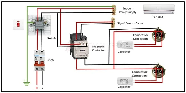
This Diagram Shows Split AC Means The Air Conditioning System Is Made Up of Two Separate Units. The Air-Cooled Condensing Unit Called The Compressor Unit Is Placed Outside The Air-Conditioned Area Whereas The Air-Handling Unit is Inside The Room Where The AC is Fixed. Split ACs are a Huge Upgrade From Traditional Window ACs.
Diagram of Split AC wiring:
Components Need for this Project:
You can get the components from any of the sites below:
- DP MCB [See Buy Click Amazon]
- Magnetic Contactor [See Buy Click Amazon]
- Gang Switch [See Buy Click Amazon]
- Capacitor [See Buy Click Amazon]
- Indoor AC [See Buy Click Amazon]
*Please note: These are affiliate links. I may make a commission if you buy the components through these links. I would appreciate your support in this way!
$ads={1}
Read Also:
Components used to make the Split AC Wiring Connection:
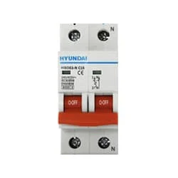
01. DP MCB
 |
| Fig 2: DP MCB |
Double pole MCB can control two wires. This circuit breaker is generally used in single-phase electric lines. Double pole MCB circuit breaker input has two wires supply two wires and an output. In a single-phase line, A double-pole MCB circuit breaker is used to give good production. This circuit breaker is provided through phase and neutral circuit breaker, it is very safe. This circuit breaker is preferred for home appliances. A DP MCB usually trips for 2 reasons 1. Overload 2. Short circuit.
02. Magnetic Contactor
 |
| Fig 3: Magnetic Contactor |
A magnetic contactor is an electrical device used for load control, automation, and protection. It is much like a magnetic reel. However, relays are generally used for low power and voltage, on the other hand, when we think of high power, these heavy-duty contractors only come to mind. It basically works by switching the load on and off. It has 3 terminals whose inputs are denoted as L1, L2, L3, and outputs as T1, T2, and T3. The circuit of the load is made in automation mode or protection using auxiliary contacts. It has two types of terminals. 1) Normally Open (NO). 2) Normally Closed (NC)
03. Gang Switch
 |
| Fig 4: Gang Switch |
A Double Pole (or DP) Switch is a Switch That Controls 2 Circuits at the Same Time. They are Essentially 2 switches in one. In terms of Residential Switching, this Normally Means it Switches the live and Neutral at the same time. Double pole (DP) Switches are often used for Appliances that Require Heavy loads. Double pole (DP) switches can also be used as a Safety Shut-off for a Residential appliance. A DP Switch has two Connections to 2 Separate Circuits.
04. Capacitor
 |
| Fig 5: Capacitor |
A Run Capacitor is Used in Single-Phase Motors to Maintain a Running Torque on an Auxiliary Coil While The Motor is Toaded. These Capacitors Are Considered Continuous Duty While The Motor is Powered And Will Remain in The Circuit While The Starts Capacitor Drops out. The Run Capacitor, Also Sometimes Called an “A/C Capacitor,” Uses Its Stored Energy to Turn or Run The fan Motor. Without The Run Capacitor, The Fan Cannot Turn. Run Capacitors Are Also Rated by Voltage Classification. The Voltage Classifications are 370V and 440V.
05. Indoor AC
 |
| Fig 6: Indoor AC |
One is an Indoor Unit And The Other is an Outdoor Unit. Evaporators are installed in indoor units and condensers are installed outdoors. So in this case the indoor unit will be inside your house and you can fit the outdoor unit into the outside wall or roof of your house. But one thing should be noted that there should be a lot of free space next to the outdoor unit. A little space is needed otherwise the heat cannot be radiated immediately. In this case, the pipeline between the indoor unit and the outdoor unit is routed through a small hole in your wall.
Thank You for visiting the website. Keep visiting for more Updates
$ads={2}
Frequently Asked Questions
What wiring is required for AC?
You can use calculations based on the Power supply AC unit's tonnage and voltage to determine the wire size. For example, a 1.5-ton AC unit with a maximum Circuit diagram wattage of 1,800W typically requires a wire size of 18 AWG, Project system while a 5-ton AC unit with a maximum wattage of 6,000W requires a wire power supply size of 10 AWG.
Can I connect 1.5 mm wire to 2.5 mm wire?
Connecting a 2.5 wire directly to a 1.5 wire can potentially cause several issues. The 2.5 wire has a larger current-carrying Circuit diagram capacity than the 1.5 wire, so if a larger current flows through the current 2.5 wire and into the 1.5 wire, it could lead to overheating and potentially cause damage to the power supply 1.5 wire.
What is the formula for calculating cable length?
The formula when using one load cell is as follows: The maximum cable length = the allowable cable resistance ÷ the cable resistance per meter.
Which tool measures cable length?
The Klein Tools Cable Length Meter is a portable Time Domain and Reflectometry (TDR) cable length power supply tester. It measures cable length, calibrates Velocity of Propagation (VoP) values, Circuit diagram finds the distance to faults in cables, and provides built-in tone generation for cable project system tracing.
What is the free length of a cable?
Free Length: The power supply amount of exposed inner wire of a cable, measured by pulling the Circuit diagram inner wire all to 1 end, if there's a rubber boot on the inner wire measuring this end of the cable make sure any adjusters are collapsed, measuring just the exposed inner wire excluding any fittings on the inner wire.


Post a Comment
Do leave your comments