Single Phase Energy Meter Wiring
Single Phase Energy Meter Wiring:
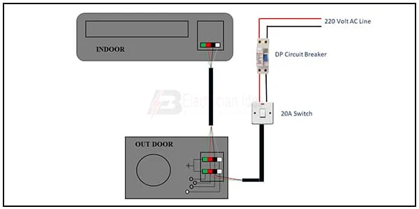
This diagram shows how to connect single-phase energy meter wiring. In this circuit diagram, we just try to describe simply how to connect a single-phase energy meter to house loads like ( light, fan ), etc. This diagram is for single-phase house wiring. So you can wire your house or office like this diagram very easily. If you want to learn how to connect this circuit clearly you can follow our youtube video link in below.
Diagram of Single Phase Energy Meter wiring:
Components Need for this Project:
You can get the components from any of the sites below:
- Single Phase Energy Meter [See Buy Click Amazon]
- DP MCB [See Buy Click Amazon]
- Switch [See Buy Click Amazon]
- Socket [See Buy Click Amazon]
- Light [See Buy Click Amazon]
- Ceiling Fan [See Buy Click Amazon]
- Fan Regulator [See Buy Click Amazon]
*Please note: These are affiliate links. I may make a commission if you buy the components through these links. I would appreciate your support in this way!
$ads={1}
Read Also:
Components used to make the Single Phase Energy Meter:
01. Single Phase Energy Meter
 |
| Fig 2: Single Phase Energy Meter |
The measuring device with the help of which the electric power or energy of a circuit is measured is called Energy Meter (Energy Meter). Also called a watt-hour or kilowatt-hour meter. For home appliances, we used a single-phase energy meter. The single-phase energy meter is directly connected between the line and the load. Both coils produce their magnetic fields, when the meter is connected to the supply line, and the load. Energy meters are used in homes and in industrial applications where we want to found that how much energy is being consumed by home appliances and electrical equipment.
02. DP MCB
 |
| Fig 3: DP MCB |
Double pole MCB can control two wires. This circuit breaker is generally used in single-phase electric lines. Double pole MCB circuit breaker input has two wires supply two wires and an output. In a single-phase line, A double-pole MCB circuit breaker is used to give good production. This circuit breaker is provided through phase and neutral circuit breaker, it is very safe. This circuit breaker is preferred for home appliances. A DP MCB usually trips for 2 reasons 1. Overload 2. Short circuit.
03. Switch
 |
| Fig 4: Switch |
A Single-Pole, Single-Throw (SPST) Switch. It's Got one Output and One Input. The Switch will Either be Closed or Completely Disconnected. SPSTs are Perfect for on-off Switching. They're also a Very Common Form of Momentary Switches. SPST Switches are Commonly Used in a Variety of Electrical Circuits and Applications, Such as Turning on And off Lights, Fans, and Other Appliances. They can Also be Used to Control the Flow of Electricity to Different Parts of a Circuit or to Switch Between Different Circuits Altogether.
04. Socket
 |
| Fig 5: Socket |
A socket is a type of equipment used in electrical wiring lines that always has an electrical connection. According to the need, it can be supplied to the electrical equipment. In case of electric iron, electric hand drill machine and electric hand grinder etc. two-pin socket with earth terminal is used. Also, three-pin sockets are used for electrical appliances that have a metal body and are likely to be electrified. Eg – Refrigerator, room heater, table heater, hot-plate, electric oven etc.
05. Light
 |
| Fig 6: Light |
CFLs work in a completely different way from ordinary lamps, they work by using a different process called fluorescence rather than generating light from heat. A typical light bulb wastes 90% of energy and converts only 10% of energy into light, this is where CFL has the biggest advantage. CFL- Curved or conical glass tube filled with argon and a small amount of mercury vapor. The inner wall of the glass is coated with fluorescent material. CFL- It is manufactured using the principle of creating fluorescent light. CFL- Originally white in color but now the construction and use of CFLs producing colored light has become popular.
06. Ceiling Fan
 |
| Fig 7: Ceiling Fan |
The main driving force behind all ceiling fan systems is the motor used inside the fan. We can also compare it with the soul of a fan. This motor converts the supplied electrical energy into mechanical energy which turns the ceiling fan and gives us air. When current is supplied, the magnetic field formed on the positive half-cycle becomes the reverse magnetic field on the next negative half-cycle. The magnitude part does not rotate and the capacitor is converted to a phase when it is connected to a phase motor or ceiling fan with a helical coil or stationing coil. When power is supplied there is a magnetic difference between the phase currents and the coils (acting as two phases) so that the motor or fan rotates.
07. Fan Regulator
 |
| Fig 8: Fan Regulator |
Reduces fan speed by switching on and off. Reducing the speed of the fan, the power Consumption is also Reduced. It is basically a wire wood resistor-based regulator. The large regulators that were used in the past took up more than half of the switchboard space and were very hot. It looks very small in size. Almost equal to a switch. Electrical regulators are basically made by winding copper wire on an iron core. As Electricity Travels Long Distances Through These Wires, Some of The Electrical Energy is Converted Into Heat Energy.
Thank You for visiting the website. Keep visiting for more Updates.
$ads={2}
Frequently Asked Questions
What is a single-phase meter?
A single-phase meter also referred to as a credit meter, KWh meter, or check meter are electrical meter designed for use in measuring the power supply consumption in a single-phase power supply. These meters, however, only deal with the Alternating current flow (AC power) supply and not the Direct current (DC) power.
How many wires are single-phase?
Remember that a single-phase system has two wires. A three-phase system has four. Another way is to check your voltage. If you have a 3-phase system, you will see readings of 120 volts between a hot wire or the ground wire.
How many lines are in a single phase?
Single-phase systems are the simplest electrical circuit diagrams. They require only two lines: one for the power supply to go in and the other is a return path for the current flow. These are often called Line 1 and Line 2, or Line 1 or Neutral.
What is the voltage in single-phase?
In a single-phase power supply, the supply of the voltage is 230 V with ±10 variation. In a 3-phase power supply, the line-to-line voltage is 440 V with ±10 variation. The power supply delivered in the single-phase power supply is pulsating.
What is the basic principle of an energy meter?
On a single-phase AC supply, the electromechanical induction meter operates through electromagnetic induction by counting the revolutions of a non-magnetic, but electrically conductive, metal disc which is made to rotate at a speed proportional to the power supply passing through the meter.
You may like these posts


Post a Comment
Do leave your comments