Series and Parallel Circuits Wiring | Series Connection Diagram
Series and Parallel Circuits Wiring:
This diagram shows how to make a series and parallel circuit wiring. In this circuit diagram, we use a fuse, 2 switches, 2 sockets, an indicator, and a light holder. First, we need an input phase line to fuse then from fuse to switches, sockets, and indicator, and then neutral connection input to the holder, indicator light, and sockets. Now, this circuit is ready for use. If you want to see this diagram for more information please check our youtube video below the post.
Diagram Series and Parallel Circuits Wiring:
 |
| Fig 1: Series and Parallel Circuits Wiring |
Components Need for this Project:
You can get the components from any of the sites below:
- Light Holder [See Buy Click Amazon]
- Fuse [See Buy Click Amazon]
- Socket [See Buy Click Amazon]
- Indicator Light [See Buy Click Amazon]
- Light [See Buy Click Amazon]
- Switch [See Buy Click Amazon]
*Please note: These are affiliate links. I may make a commission if you buy the components through these links. I would appreciate your support in this way!
$ads={1}Read Also:
Components used to make the Series and Parallel Circuits Wiring:
01. Light Holder
 |
| Fig 2: Light Holder |
A Light holder, commonly referred to as a stockholder, is any person, company, or institution that owns at least one share of a company's stock. Light Holders own the company, they enjoy the benefits of the company's success in the form of increased stock appreciation. Unlike owners of sole proprietorships or partnerships, corporate Light holders are not personally liable for the company's debts and other financial obligations. If the company goes bankrupt, its creditors cannot demand payment from the Light holders.
02. Fuse
 |
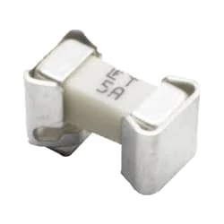
| Fig 3: Fuse |
Fuses have Been Used as Essential Safety Devices From the Early Days of Electrical Engineering. Today There are Thousands of Different fuse Designs Which have Current Voltage ratings, Breaking Capacity, and Response Times, Depending on the Application. Electricity Component Current Operating Characteristics of Fuses are Chosen to Provide Adequate Protection Without Needless Interruption. House Wiring regulations usually define a Maximum fuse Current rating for Particular Circuits. When a Damaged live Wire Makes contact with a Metal Case that is connected to the Ground. A Short Circuit will Form and The Fuse will Melt.
03. Socket
 |
| Fig 4: Socket |
A socket is a type of equipment used in electrical wiring lines that always has an electrical connection. According to the need, it can be supplied to the electrical equipment. In case of electric iron, electric hand drill machine and electric hand grinder etc. two-pin socket with earth terminal is used. Also, three-pin sockets are used for electrical appliances that have a metal body and are likely to be electrified. Eg – Refrigerator, room heater, table heater, hot-plate, electric oven etc.
04. Indicator Light
 |
| Fig 5: Indicator Light |
An electric current Flow Indicator Senses The electrical Current Through an electrical device And produces visible feedback to Indicate Proper Operation. The Current Flow Indicator Has Voltage And Current Regulation Craving First And Second Inputs Connected To The First And Second Conductors, Respectively. This Publication Provides updated Statistics on a Comprehensive Set of social, Economic, Financial, and Environmental Measures as Well as Select Indicators for Sustainable Development Goals.
05. Light
 |
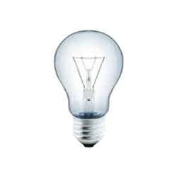
| Fig 6: Light |
CFLs work in a completely different way from ordinary lamps, they work by using a different process called fluorescence rather than generating light from heat. A typical light bulb wastes 90% of energy and converts only 10% of energy into light, this is where CFL has the biggest advantage. CFL- Curved or conical glass tube filled with argon and a small amount of mercury vapor. The inner wall of the glass is coated with fluorescent material. CFL- It is manufactured using the principle of creating fluorescent light. CFL- Originally white in color but now the construction and use of CFLs producing colored light has become popular.
06. Switch
 |
| Fig 7: Switch |
A Single-Pole, Single-Throw (SPST) Switch. It's Got one Output and One Input. The Switch will Either be Closed or Completely Disconnected. SPSTs are Perfect for on-off Switching. They're also a Very Common Form of Momentary Switches. SPST Switches are Commonly Used in a Variety of Electrical Circuits and Applications, Such as Turning on And off Lights, Fans, and Other Appliances. They can Also be Used to Control the Flow of Electricity to Different Parts of a Circuit or to Switch Between Different Circuits Altogether.
Thank You for visiting the website. Keep visiting for more Updates
$ads={2}
Frequently Asked Questions
What is series circuit wiring?
A series circuit diagram is one in which all circuit elements are arranged in a single path. In a series circuit, the current flow through all elements is the same, but the voltage of the drop across each element is different.
What is a combination of series and parallel wiring?
It is a unique type of circuit diagram that is connected in both series and parallel ways. The current flow remains the same throughout the circuit diagram, and the sum of voltage all across the three resistors is equal to the other points of the voltage.
What are 2 major differences between series and parallel circuits?
In a series circuit diagram, the components are connected in a line, and the same current flows through all of them. In a parallel circuit diagram, the components are connected so that each component has its own separate branch or the same voltage is applied to each component.
Which is better series or parallel?
Answer and Explanation: In a parallel circuit, every appliance is connected to the battery or the supply. Also, there is the same voltage across each of the appliances. A parallel circuit diagram is better than a series circuit because in case of any failure only the appliance connecting the faulty pathway will stop working.
Why is parallel better than series?
(i) In parallel combination each appliance gets the full of the voltage. (ii) If 1 appliance is switched on, others are not affected. (iii) The parallel circuit divides the current flow through the appliances. Each appliance gets proper current flow depending on its resistance.


Post a Comment
Do leave your comments