How To Make Godown Wiring Circuit Diagram | Godown wiring
How To Make Godown Wiring Circuit Diagram:
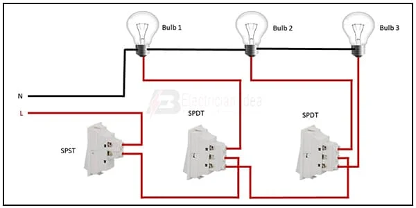
This diagram shows how to make a godown wiring circuit diagram. In this circuit, we use an SPST switch ( single pole double throw ), 2 SPDT switches, and 3 lights. Here we just input phase connection in switches and then connect to light then neutral wire input to light. If you want more clear details about this circuit diagram please check our youtube video in the below article.
Diagram of Godown Circuit Diagram wiring:
Components Need for this Project:
You can get the components from any of the sites below:
- SPST Switch [See Buy Click Amazon]
- SPDT Switch [See Buy Click Amazon]
- Light [See Buy Click Amazon]
*Please note: These are affiliate links. I may make a commission if you buy the components through these links. I would appreciate your support in this way!
$ads={1}Read Also:
Components used to make the Godown Wiring Circuit Diagram:
01. SPST Switch
 |
| Fig 2: SPST Switch |
A Single-Pole, Single-Throw (SPST) Switch. It's Got one Output and One Input. The Switch will Either be Closed or Completely Disconnected. SPSTs are Perfect for on-off Switching. They're also a Very Common Form of Momentary Switches. SPST Switches are Commonly Used in a Variety of Electrical Circuits and Applications, Such as Turning on And off Lights, Fans, and Other Appliances. They can Also be Used to Control the Flow of Electricity to Different Parts of a Circuit or to Switch Between Different Circuits Altogether.
02. SPDT Switch
 |
| Fig 3: SPDT Switch |
The principle of SPDT or Double Pole Single Throw Switch is to control two different circuits simultaneously using a single actuator like a pushbutton, toggle, etc. Both circuits are turned on or off. These switches have four terminals with two outputs and two inputs. It is possible to have different Voltages from different sources Connected to a single Double Pole Single switch. This switch accepts two inputs that can drive two different outputs in a circuit. They are essentially two SPST switches built as one, affecting separate circuits but controlled by the same actuator
03. Light
 |
| Fig 4: Light |
CFLs work in a completely different way from ordinary lamps, they work by using a different process called fluorescence rather than generating light from heat. A typical light bulb wastes 90% of energy and converts only 10% of energy into light, this is where CFL has the biggest advantage. CFL- Curved or conical glass tube filled with argon and a small amount of mercury vapor. The inner wall of the glass is coated with fluorescent material. CFL- It is manufactured using the principle of creating fluorescent light. CFL- Originally white in color but now the construction and use of CFLs producing colored light has become popular.
Thank You for visiting the website. Keep visiting for more Updates
$ads={2}
Frequently Asked Questions
How do you draw a wiring diagram?
Draw connecting wires as straight lines. Use a dot to indicate line junction, and use line jumps to indicate cross lines that are not connected; Label components such as resistors or capacitors with their values.
How is a simple circuit made?
A simple electric circuit diagram can consist of a battery (and another energy source), a light bulb (or another device that uses energy), or conducting wires that connect the two terminals of the battery to the 2 ends of the light bulb.
How a circuit works step by step?
An electric circuit diagram has to have a power source, wires for the electricity to flow through, and a device such as a lamp or a motor that uses the electric current flow. All of these parts must be connected so that the current flow continues to flow. For small portable devices such as flashlights, a battery supplies the power supply.
How does a circuit start?
Typically a circuit diagram starts with a power source of some kind, and that power supply source provides a voltage that is rated in volts. For example, let's say we have a 9v battery. The voltage is the electrical potential that a battery or a power supply source has.
How are circuit boards printed?
All printed circuit diagram boards are built from alternating layers of conductive copper with layers of electrically insulating material. During manufacturing, the inner copper layers are etched, leaving the intended traces of copper for connecting components in the circuit diagram board.


Post a Comment
Do leave your comments