Submersible Motor Control Box Connection | Control Box for Motor
Submersible Motor Control Box Connection:
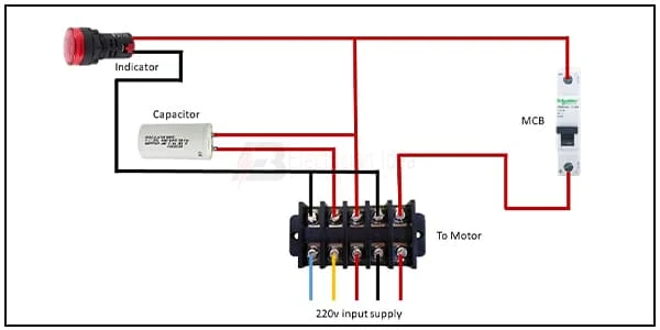
This circuit diagram shows how to connect the submersible motor control box connection. In this diagram, we use an indicator light, a capacitor, an SP MCB, and a terminal block. This diagram is very simple to connect. If you want to connect this diagram and want to see this diagram animation please check out the youtube video at the below link.
Diagram of Submersible Motor Control Box wiring:
 |
| Fig 1: Submersible Motor Control Box Connection |
Components Need for this Project:
You can get the components from any of the sites below:
- SP MCB [See Buy Click Amazon]
- Capacitor [See Buy Click Amazon]
- Indicator Light [See Buy Click Amazon]
- Terminal Block [See Buy Click Amazon]
*Please note: These are affiliate links. I may make a commission if you buy the components through these links. I would appreciate your support in this way!
$ads={1}Read Also:
Components used to make the Submersible Motor Control Box:
01. SP MCB
 |
| Fig 2: SP MCB |
MCB SP means single pole it protects only one phase switching. MCB (Miniature Circuit Breaker) Curswitch is the most basic general-purpose switch that you use to control a light or another device from one location. These Switches Have Two Brass-Colored Screw Terminals Connected to the hot Power Source Wires. (MCB) For any Distribution Board, the Protection System Must be Used in The Incomer. Phase and Neutral Single Phase Supply to break. 120-volt circuits, 15-20 amp single pole breaker is typically used.
02. Capacitor
 |
| Fig 3: Capacitor |
A Run Capacitor is Used in Single-Phase Motors to Maintain a Running Torque on an Auxiliary Coil While The Motor is Toaded. These Capacitors Are Considered Continuous Duty While The Motor is Powered And Will Remain in The Circuit While The Starts Capacitor Drops out. The Run Capacitor, Also Sometimes Called an “A/C Capacitor,” Uses Its Stored Energy to Turn or Run The fan Motor. Without The Run Capacitor, The Fan Cannot Turn. Run Capacitors Are Also Rated by Voltage Classification. The Voltage Classifications are 370V and 440V.
03. Indicator Light
 |
| Fig 4: Indicator Light |
An electric current Flow Indicator Senses The electrical Current Through an electrical device And produces visible feedback to Indicate Proper Operation. The Current Flow Indicator Has Voltage And Current Regulation Craving First And Second Inputs Connected To The First And Second Conductors, Respectively. This Publication Provides updated Statistics on a Comprehensive Set of social, Economic, Financial, and Environmental Measures as Well as Select Indicators for Sustainable Development Goals.
04. Terminal Block
 |
| Fig 5: Terminal Block |
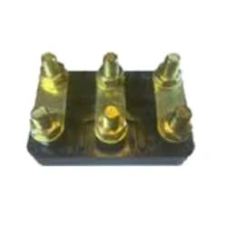
A Terminal Block Consists of Modular Housing With An Insulated Body That Secures Two Or More Wires Together. Terminal Blocks—Also Referred to as terminal Connectors, Connection Terminals, or Screw Terminals—are Used in a Wide Array of Applications Where Electrical Systems Need to be Safely Connected. Electrical Terminals are a Class of Electrical Connectors That are Used to Transfer Electrical Current From a Power or Grounding Source to use. Terminals "Terminate" by Crimping or Soldering to Wire or Cable.
Thank You for visiting the website. Keep visiting for more Updates
$ads={2}
Frequently Asked Questions
What is the control box for a submersible pump?
Protects submersible pumps from low and high voltage, a drop in water level, low yield wells, clogged well screens, malfunctioning pumps or motors, and rapid cycling. Pump control boxes usually have microprocessors that monitor power supply -line voltage and pump motor for the power supply draw.
How is the submersible pump connected?
Submersible Motors are supplied with a 3-core PVC insulated flat cable of length three meters. The free end of the three-core cable of the motor needs to be connected to the supply cable from the control panel. As this joint was always nearly submerged in the water, the joint needs to be waterproof.
How is the submersible pump connected?
Submersible Motors are supplied with a three-core PVC insulated flat cable of length 3 meters. The free end of the three-core cable of the motor needs to be connected to the supply cable from the control panel. As this joint was always nearly submerged in water, the joint needs to be waterproof.
What is a pump control panel?
A Pump Control Panel is used in the automation of the machinery in motor control and applications that are a part of water-based systems. This type of control panel consists of several power components that control the function of the pump motor, and also the various devices for operator control.
How does a pump controller work?
The controller controls the pump speed or thus the output of the pump. The input variables were given by various sensors, such as flow meters or level sensors. The information triggers the pump and controller, which then adjusts the speed of the pump to the optimal.


Post a Comment
Do leave your comments