Inverter Connection for Home
This Diagram shows the Inverter connection for Home. An inverter is an electrical device that converts DC current into alternating current (AC). AC can be operated at any voltage and frequency system with suitable transformers, switches, and control circuits. Most electrical appliances run on AC (Alternative Current). Nowadays inverter is a very common device that is used to change the voltage in any type of machine or to control the speed of the induction motor. In this Diagram we describe how to connect an inverter with a magnetic contactor and grid line for output.
Inverter Connection for Home wiring
Components Need for this Project:
You can get the components from any of the sites below:
- Single Phase Energy Meter [See Buy Click Amazon]
- Magnetic Contactor [See Buy Click Amazon]
- Inverter [See Buy Click Amazon]
$ads={1}
Read Also:
Components used to make the Inverter Connection for Home:
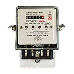
01. Single Phase Energy Meter
 |
| Fig 2: Single Phase Energy Meter |
02. Magnetic Contactor
 |
| Fig 3: Magnetic Contactor |
03. Inverter
 |
| Fig 4: Inverter |
Thank You for visiting the website. Keep visiting for more Updates.
Frequently Asked Questions
Since exposure to direct sunlight could cause overheating of the components, it can reduce the inverter efficiency. So, choose a shady spot away from direct sunlight. Not only does it enhance inverter efficiency, but it also promotes lifespan.
If you're wondering if a solar inverter could run without batteries, the short answer is yes it can! If you choose to install a hybrid solution that uses solar energy to convert Solar energy into an AC power supply using your Hybrid inverter. This only works when you have sufficient Sun or if you have Solar panels.
Four AWG battery cables should be used on power supply inverters rated up to 1500 watts and most commonly used on 900, 1000, 1100, and 1200-watt inverters. Smaller-sized an inverter generally comes with a short 6 AWG cable which is included with the inverter.
You can easily estimate the size inverter you will need by adding up the largest number of watts you'll be using at a given time or adding 20%. For example, let is say you need 1,500 watts to run your computer or microwave at the same time. Take 1,500 + 300 (which is 20% of 1,500) = 1,800 watts.
A hybrid solar inverter is a piece of equipment that is created by combining a solar inverter or a battery inverter into a single unit. This allows the hybrid solar inverter to intelligently handle the power supply coming from your solar panels, solar batteries, and the utility grid all at the same time.
You may like these posts

DP MCB, an Energy meter, sockets, a switch, etc. If you want

In this circuit, we use 2 capacitors, one voltage relay,

In this diagram, we use a ceiling fan a speed controller,

In this circuit, we use a circuit breaker, a light, a contactor,

In this circuit, we use 2 lights and one switch, and one SP MCB

light with a 2-way switch. In this circuit diagram, we use


Post a Comment
Do leave your comments