3 phase Motor with Single phase Supply
3 Phase Motor with Single Phase Supply
This diagram shows 3 phase motor with single phase supply. When you want to run a three-phase device to a single-phase power supply, you'll need to use a formula. The formula like as (3–1) x (240 – 110) = 260v. So, if you have a three-phase device that is currently running at 220v, you would need to convert it to a single phase using the formula. If you still want to drive the 3-phase motor on a single-phase supply, you must use a variable frequency drive (VFD), phase shifter or converter, or simply a capacitor which is used to make the phase difference (a capacitor is used for the same purpose as in a ceiling fan).
3 Phase Motor with Single Phase Power Supply Run wiring
Components Need for this Project:
You can get the components from any of the sites below:
- Magnetic Contactor [See Buy Click Amazon]
- 50 MFD Cpacitor [See Buy Click Amazon]
- 3 Phase Motor [See Buy Click Amazon]
- NC Switch [See Buy Click Amazon]
- NO Switch [See Buy Click Amazon]
*Please note: These are affiliate links. I may make a commission if you buy the components through these links. I would appreciate your support in this way!
$ads={1}Read Also:
Components used to make the 3 phase Motor in 1 phase Supply:
01. Magnetic Contactor
 |
Fig 2: Magnetic Contactor
|
A magnetic contactor is an electrical device used for load control, automation, and protection. It is much like a magnetic reel. However, relays are generally used for low power and voltage, on the other hand, when we think of high power, these heavy-duty contractors only come to mind. It basically works by switching the load on and off. It has 3 terminals whose inputs are denoted as L1, L2, L3, and outputs as T1, T2, and T3. The circuit of the load is made in automation mode or protection using auxiliary contacts. It has two types of terminals. 1) Normally Open (NO). 2) Normally Closed (NC)
02. 50 MFD Capacitor
 |
| Fig 3: 50 MFD Capacitor |
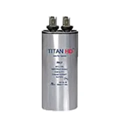
An MFD or Micro-Farad is a Technical Terminology Used to Describe the Level of Capacity in a Capacitor. Therefore, The Higher The MFD Ratings of a Capacitor, The More Electrical Current Your Capacitor Can Store. A Standard Capacitor may Have an MFD Ranging from 5 to 80 MFD. 50 MFD Volts Which Means it will Work at 370 or 440 VAC. A Dual-Run Capacitor, Such as This 50uf, Combines two Capacitors Into One Unit. 50 MFD 250 Volt Round Capacitor With Mounting Stud and Capacitor has two Screw-type Terminals02. 50 MFD Capacitor
03. 3 Phase Motor
 |
| Fig 4: 3 Phase Motor |
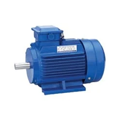
A Three-Phase Motor is an Electric Motor That Typically Receives its Power From a Three-Phase System (three-phase current) This can be realized via a Three-Phase Mains Supply or a Frequency Inverter. Three-Phase Motors are Available as Synchronous and Asynchronous Motors. Three Phase Alternating Current Power Motor is Economical to Supply Power to the data Center Since it Requires Less Conductor Material to Supply Electricity. This Explains Why 3 Phase Alternating Current Motor is Used in Electric Transmission, Generation, and Distribution in Most Countries Worldwide.
04. NC Swtich |
| Fig 5: NC Switch |
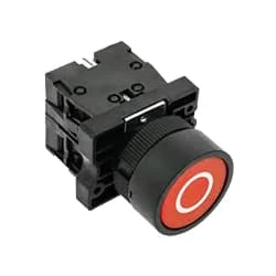
Indicates the contacts of switches or automatic actionable devices. Simply put, the push switches, magnetic contactors, and relays that we use in the factory Normally have Close Contact exists. At this moment the switch will be in normally closed condition. Because already he is sitting close. When turned off the contact will open. To make ladder logic you need to understand NC contact. As already explained. The switch contact is already closed in NC. That is enough to understand.
05. NO Swtich
 |
| Fig 6: NO Switch |
The operator switch has its contact in Normally Open condition. To make Ladder Logic you need to understand NO contact. A Classic Switch has one Input And one Output. In "No Switch," YoungBoy Raps About Ammunition, Murder, Firearms, and Firearm Attachments Such as a Switch. The contact of the switch whose contact is already open is NO. That is enough to understand. no switch in a circuit, then the circuit will not function as intended. to write a program such that when the red light is on, This switch is now in normally open condition. When you push the switch it will close and the red light will turn on.
Thank You for visiting the website. Keep visiting for more Updates
$ads={2}
Frequently Asked Questions
Can you run a 3-phase motor on a single-phase?
You cannot directly wire a 3-phase motor to a single-phase power supply. However, you can get a single-phase VF (variable voltage variable frequency) device which will convert single-phase power to a 3-phase power supply provided that only a modest amount of power is required.
Can you change a 3-phase electric motor to single-phase?
Use a 3-phase to single-phase converter: A phase converter can be wired directly to whatever motor you're trying to convert. You'll first run 2 wires from the motor to the converter and then from the converter to your supply.
Can I run a 3-phase motor on 220v?
Yes it can, The motor has to be a 220/380 Volts rated motor with 6 terminals. The motor has to be set up in Delta connection, and the 3rd phase has to be excited with Capacitors to get the phase shift for the motor to start. Roughly 55 to 100 µF per kW.
How to convert 3-phase to 240?
You would need a transformer that is specifically designed to convert a 3-phase power supply to single-phase power at the desired voltage. This type of transformer will have the ability to take the 208V three-phase input and provide a 240V single-phase output.
Can VFD convert single-phase to 3-phase?
Variable Frequency Drives (VFD) are designed to allow adjustable the motor input frequency and voltage. They're available for both single- and 3-phase power input, with most modern VFDs able to convert single-phase power to 3-phase.


Post a Comment
Do leave your comments