Light Breightness Control wiring:
Power is in the correct direction to flow through the LED Dc 12V power supply. The brightness is determined by the current control line or the speed of the flow of the Potentiometer resistor of the power supply using Battery 12v. The more electrons filling holes, the more photons are released, and the higher the brightness output 12v dc line.
Digram of Light Breightness control Circuit:
Components Need for this Project:
You can get the components from any of the sites below:
- Potentiometer [See Buy Click Amazon]
- Regulator [See Buy Click Amazon]
- Resistor [See Buy Click Amazon]
- DC Light [See Buy Click Amazon]
Read Also:
Components used to make the Light Breightness Control:
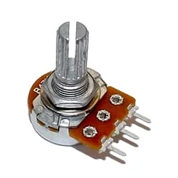
01. Potentiometer
 |
| Fig 2: Potentiometer |
A Variable Resistor is a Type of Resistor Whose Electrical Resistance Value Can be Adjusted On Demand. Variable Resistors are Used in An Electronic Circuit to Adjust Circuit Resistance as a Means to Control The Voltage or Current Within a Circuit. The electrical resistance is Varied by Sliding a Wiper contact Along a Resistance Track. Sometimes the Resistance is Adjusted at a Preset value as Required at the Time of the Circuit Building by Adjusting the Screw Attached to it and Sometimes Resistance can be Adjusted When Required by Controlling The Knob Connected to it.
02. Regulator
 |
| Fig 3: Regulator |
The main component of an electrical regulator is a Triac. Power is supplied to the load by cutting a certain portion of the supply AC voltage wave through this Triac. As a result, power is not supplied to the load throughout the complete cycle i.e. 360 degrees, but power is supplied to the load for a shorter period than that. This reduces the average power delivered to the load over a period of time and slows down the fan speed. To install the fan regulator, put the phase wire from the fan switch (phase wire means the red is used as the current wire) to the regulator, and the other wire from the regulator to the phase wire of the fan.
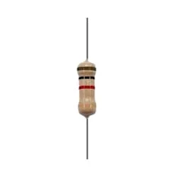
03. Resistor
 |
| Fig 3: Resistor |
The main function of a resistor is to block the flow of current or cause a voltage drop in an electronic circuit. In short, the function of the register is to prevent the movement of electricity. When we know about electronics, the first name that comes is Resistor. It is basically a common component of electronics. This component is used in every electronic circuit. A resistor is a very familiar component to those who work with electronics. It has a special function. Resistance is denoted by R. Its unit is the ohm (Ω). The following figure shows some resistor symbols that are used in various circuit boards and circuit diagrams.
04. DC Light
 |
| Fig 5: Dc Light |
LED (light emitting diode) is basically a type of diode that emits light at a certain voltage. These LED bulbs turn on at a very low voltage such as 2~3 volts. When the light emitting diode is forward biased, the free electrons in the n-type semiconductor gain electrical energy from the DC source and move from the balance band to the conduction band and the electrical Under the influence of pressure, current flows through the junction to P-type. In the p-type majority of carrier holes are located in the valence band. Thus basically the p-n junction becomes a light source.
Thank You for visiting the website. Keep visiting for more Updates.


Post a Comment
Do leave your comments