Timer Testing Wiring | street light timer
Timer Testing Wiring:
Timed Relays are Used in Applications Where it is necessary to Delay the Execution of Some Events. These May Include Industrial Control Circuits, Security Systems, Burglar Alarms, And Automated Lighting Control Systems. Time Relays Can Be Either Electromechanical or Solid-State And Analog or Digital.
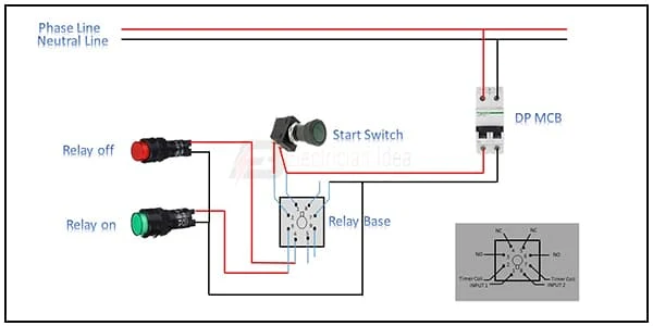
Diagram of Timer Testing wiring:
 |
| Fig 1: Timer Testing Wiring |
Components Need for this Project:
You can get the components from any of the sites below:
- DP MCB [See Buy Click Amazon]
- Relay [See Buy Click Amazon]
- Star Switch [See Buy Click Amazon]
- Indicator Lamp [See Buy Click Amazon]
*Please note: These are affiliate links. I may make a commission if you buy the components through these links. I would appreciate your support in this way!
$ads={1}Read Also:
Components used to make the Timer Testing Wiring :
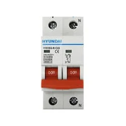
01. DP MCB
 |
| Fig 2: DP MCB |
Double pole MCB can control two wires. This circuit breaker is generally used in single-phase electric lines. Double pole MCB circuit breaker input has two wires supply two wires and an output. In a single-phase line, A double-pole MCB circuit breaker is used to give good production. This circuit breaker is provided through phase and neutral circuit breaker, it is very safe. This circuit breaker is preferred for home appliances. A DP MCB usually trips for 2 reasons 1. Overload 2. Short circuit.
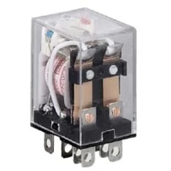
02. Relay
 |
| Fig 3: Relay |
This relay is known as 8 pin relay because it has 8 terminals. When coil power is supplied. A magnetic induction is created due to which the connected sheet of the Com part moves towards the NO part changing to NO-NC. The former NC region loses conductivity and becomes NO. Thus, as long as power is supplied to the coil, the NO and NC positions will remain in the alternating state, and when the power is removed from the coil, it will return to its original position. This is basically how a relay switch works.
03. Star Switch
 |
| Fig 4: Star Switch |
The operator switch has its contact in Normally Open condition. To make Ladder Logic you need to understand NO contact. A Classic Switch has one Input And one Output. In "No Switch," YoungBoy Raps About Ammunition, Murder, Firearms, and Firearm Attachments Such as a Switch. The contact of the switch whose contact is already open is NO. That is enough to understand. no switch in a circuit, then the circuit will not function as intended. to write a program such that when the red light is on, This switch is now in normally open condition. When you push the switch it will close and the red light will turn on.
04. Indicator Lamp
 |
| Fig 5: Indicator Lamp |
An electric current Flow Indicator Senses The electrical Current Through an electrical device And produces visible feedback to Indicate Proper Operation. The Current Flow Indicator Has Voltage And Current Regulation Craving First And Second Inputs Connected To The First And Second Conductors, Respectively. This Publication Provides updated Statistics on a Comprehensive Set of social, Economic, Financial, and Environmental Measures as Well as Select Indicators for Sustainable Development Goals.
Thank You for visiting the website. Keep visiting for more Updates
$ads={2}
Frequently Asked Questions
What is an electrical timer?
A timer is a small device that automatically opens and closes an electrical circuit diagram for a specific period of time. In short, we could say that it allows you to program the on or off switching of different devices in a simple manner.
What is the working principle of a timer?
A Timer is a control device that outputs a signal at a preset time after an input and signal are received. The pointers on the Timer do not move the along with time like the hands of a clock do. You cannot see the progression of the time.
What is a timer system?
Overview. Timers are peripheral devices that could be used to set the interval between events. In embedded systems design, the ability to precisely set the timing between events was extremely common. Timers are used in multi-3rd operating systems to determine how long a task is active before swapping to a new task.
Where are electrical timers used?
Timers are devices that can switch on or off an electrical circuit diagram after a preset or variable time interval. They are widely used in electrical controls for various applications, such as lighting, heating, cooling, motor control or automation, and safety.
How do you calculate the timer value?
Simply put, do your arithmetic to calculate the desired 16-bit timer value, and then divide the 16-bit value into the two 8-bit bytes that comprise the 16-bit value. In decimal, the TH register is the 16-bit timer value divided by 256, and the TL register takes the 16-bit timer value modulo 256.


Post a Comment
Do leave your comments