Float Switch connection in Water Pump | Pump float switch wiring
Float Switch connection in Water Pump:
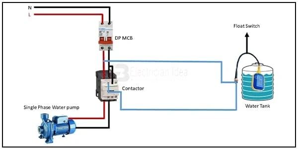
This diagram shows how to connect a float switch connection in a water pump. Here we use a magnetic contactor, a DP MCB ( Double Pole Miniature Circuit Breaker ), a single-phase water pump, a float switch, and a water tank. If you want to see this circuit diagram animation connection please see our youtube video below the post.
Diagram of Float Switch connection in Water Pump wiring:
Components Need for this Project:
You can get the components from any of the sites below:
- Magnetic Contactor [See Buy Click Amazon]
- Single Phase Motor [See Buy Click Amazon]
- DP MCB [See Buy Click Amazon]
- Float Switch [See Buy Click Amazon]
*Please note: These are affiliate links. I may make a commission if you buy the components through these links. I would appreciate your support in this way!
$ads={1}Read Also:
Components used to make the Float Switch connection in Water Pump:
01. Magnetic Contcator
 |
| Fig 2: Magnetic Contcator |
A magnetic contactor is an electrical device used for load control, automation, and protection. It is much like a magnetic reel. However, relays are generally used for low power and voltage, on the other hand, when we think of high power, these heavy-duty contractors only come to mind. It basically works by switching the load on and off. It has 3 terminals whose inputs are denoted as L1, L2, L3, and outputs as T1, T2, and T3. The circuit of the load is made in automation mode or protection using auxiliary contacts. It has two types of terminals. 1) Normally Open (NO). 2) Normally Closed (NC).
02. Single Phase Motor
 |
| Fig 3: Single Phase Motor |
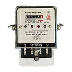
The measuring device with the help of which the electric power or energy of a circuit is measured is called Energy Meter (Energy Meter). Also called a watt-hour or kilowatt-hour meter. For home appliances, we used a single-phase energy meter. The single-phase energy meter is directly connected between the line and the load. Both coils produce their magnetic fields, when the meter is connected to the supply line, and the load. Energy meters are used in homes and in industrial applications where we want to found that how much energy is being consumed by home appliances and electrical equipment.
<
03. DP MCB
 |
| Fig 4: DP MCB |
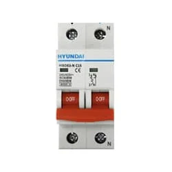
Double pole MCB can control two wires. This circuit breaker is generally used in single-phase electric lines. Double pole MCB circuit breaker input has two wires supply two wires and an output. In a single-phase line, A double-pole MCB circuit breaker is used to give good production. This circuit breaker is provided through phase and neutral circuit breaker, it is very safe. This circuit breaker is preferred for home appliances. A DP MCB usually trips for 2 reasons 1. Overload 2. Short circuit.
04. Float Switch
 |
| Fig 5: Float Switch |
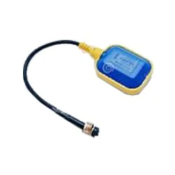
Float switch The water tank can basically be controlled with this switch. It basically works like a switch. This float switch has a magnetic reed sensor. Float Switch It is a water level controller. With this, you can create interesting projects. The Float Switch is Behind the Panel at The Bottom of the Dishwasher door, directly under the float. With this float switch, you can control the water tank motor/pump motor of your house in which water is raised in the tank.
Thank You for visiting the website. Keep visiting for more Updates.
$ads={2}
Frequently Asked Questions
How many wires does a float switch have?
We recommend using a piggy-back float switch and control panel to operate 230V pumps. DO NOT USE THE METHOD DESCRIBED BELOW FOR 230V of the PUMPS. In 115V wiring, there are 3 wire legs: 1) Hot 2) Neutral, and 3) Ground. The pump will have these 3 wires or the incoming power supply will have these 3 wires.
Do float switches need power?
Also known as the liquid level of the sensors, these products contain a hermetically sealed reed switch within a stem. An external float, with a magnet inside, passes over or activates the reed switch as the liquid level moves up and down. This is shown in the below circuit diagram. No power supply is required to operate the switches.
Can float switch work without a contactor?
In most cases, a float switch is insufficient for the task since it would be designed as part of a control circuit diagram, not a supply circuit. Use a correctly rated contactor to supply the power for the pump, and use the float switch to turn the power supply on/off to the contactor coil.
What are the parts of a float switch?
A float switch consists of a hollow floating body or an internal switch, also called a sensor. The most common internal switch is a reed switch that has a magnet inside the body. There are other internal switches of the types, but all of these switches use the same working principle.
What are the components of a float switch?
Float switches have a reed switch or a pivoted magnet and could be used for normally open (N/O) or normally closed (N/C) operations. The switch action could be reversed rotating the switch through 180°.


Post a Comment
Do leave your comments