Automatic on-off water pump relay | automatic on-off floatless relay wiring
Automatic on-off water pump relay wiring:
This Diagram shows An Automatic Water Pump Pressure Controller is an Intelligent and Economical System Designed for Water Pressure Management. It Helps Prevent Delays, Minimize Vibrations, and Allow for Precise and Accurate Control of Your Water Supply. Here's an Automatic Water Pump Controller Circuit That Controls The Water Pump Motor. The Motor Gets Automatically Switched On When Water In The Overhead Tank (OHT) Falls below The Lower limit.
Diagram of Automatic on-off water pump relay wiring:
 |
| Fig 1: Automatic on-off water pump relay wiring |
Components Need for this Project:
You can get the components from any of the sites below:
- DP MCB [See Buy Click Amazon]
- Magnetic Contactor [See Buy Click Amazon]
- Relay [See Buy Click Amazon]
- Single Phase Motor [See Buy Click Amazon]
*Please note: These are affiliate links. I may make a commission if you buy the components through these links. I would appreciate your support in this way!
$ads={1}
Read Also:
Components used to make the Automatic on-off water pump relay wiring:
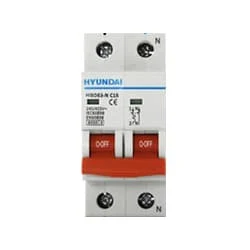
01. DP MCB
 |
| Fig 2: DP MCB |
Double pole MCB can control two wires. This circuit breaker is generally used in single-phase electric lines. Double pole MCB circuit breaker input has two wires supply two wires and an output. In a single-phase line, A double-pole MCB circuit breaker is used to give good production. This circuit breaker is provided through phase and neutral circuit breaker, it is very safe. This circuit breaker is preferred for home appliances. A DP MCB usually trips for 2 reasons 1. Overload 2. Short circuit.
02. Magnetic Contactor
 |
| Fig 3: Magnetic Contactor |
A magnetic contactor is an electrical device used for load control, automation, and protection. It is much like a magnetic reel. However, relays are generally used for low power and voltage, on the other hand, when we think of high power, these heavy-duty contractors only come to mind. It basically works by switching the load on and off. It has 3 terminals whose inputs are denoted as L1, L2, L3, and outputs as T1, T2, and T3. The circuit of the load is made in automation mode or protection using auxiliary contacts. It has two types of terminals. 1) Normally Open (NO). 2) Normally Closed (NC)
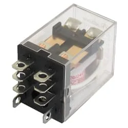
03. Relay
 |
| Fig 4: Relay |
This relay is known as 8 pin relay because it has 8 terminals. When coil power is supplied. A magnetic induction is created due to which the connected sheet of the Com part moves towards the NO part changing to NO-NC. The former NC region loses conductivity and becomes NO. Thus, as long as power is supplied to the coil, the NO and NC positions will remain in the alternating state, and when the power is removed from the coil, it will return to its original position. This is basically how a relay switch works.
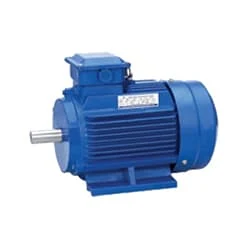
04. Single Phase Motor
 |
| Fig 5: Single Phase Motor |
Single-Phase Induction Motor is Very Simple in Construction, Economical, Reliable, and Easy to Repair And Maintain. Due to all these advantages, it is widely used in vacuum cleaners, fans, centrifugal pumps, blowers, washing machines, etc. It can run only by supplying 1 phase current through this motor. The main two parts of this motor are Rotor and Stator. Among them, the rotating part is the Rotor and the stationary part is the Stator. Like all induction motors, a single-phase induction motor consists of two main parts, the stator, and the rotor.
Thank You for visiting the website. Keep visiting for more Updates
$ads={2}
Frequently Asked Questions
What is the function of the relay in a water pump?
A pump relay acts like a switch that the power supply controller can turn on to provide a power supply to the pump. Since the controller outputs 24Volts AC power, and most pumps require a Circuit diagram anywhere from 110-220 Volts AC, as the pump relay acts as a step-up transformer to route additional power supply to the pump and activate it.
How do you control a water pump with a relay?
To use a relay to control a water pump with an Arduino, as you will need to connect the Circuit diagram relay to the Arduino's digital output pins. The Circuit diagram relay typically has 3 pins, VCC, GND, and IN. VCC should be connected to 5V of the Arduino, GND to GND, and into a digital pin of the Arduino.
What are the 3 basic functions of a relay?
Relay is an electrical control device, which has the interaction between the input circuit and the output circuit. It plays the role of automatic power supply adjustment, safety protection, and conversion circuits in the circuit diagram.
What device turns the pump on and off?
Once installed, the pump is turned on and off by water pressure, which is controlled by a pressure switch. If the water pressure is too low, the pump turns on. If the water pressure is too high, the pump turns off. This process of turning on and off is called cycling.
Why is the water pump not turning off?
If your pressure control Currenttlou switch is faulty (usually a result of clogged tubing or burned Power supply contact points), or if someone adjusted the cut-out pressure to be above the Circfuit diagram pump's capacity, your pump will run non-stop.


Post a Comment
Do leave your comments