
3 Phase Motor Starter wiring:
This diagram shows how to make 3 Phase Motor Starter Wiring. In this circuit, we use a TP MCB ( Tripple Pole Minature Circuit Breaker ), a selector switch, a magnetic contactor, and a 3-phase motor. First, we need to connect TP MCB ( Tripple Pole Miniature Circuit Breaker ), then connect the contactor with TP MCB, then connect a selector switch and motor.
Diagram of 3 Phase Motor wiring:
 |
| Fig 1: 3 Phase Motor Starter Wiring |
Components Need for this Project:
You can get the components from any of the sites below:
- FT MCB [See Buy Click Amazon]
- Contactor [See Buy Click Amazon]
- Selector Switch [See Buy Click Amazon]
- 3 Phase Motor [See Buy Click Amazon]
Read Also:
Components used to make the 3 Phase Motor wiring:
01. FT MCB
 |
| Fig 2: FT MCB |
Four pole MCCB for Four wires connections, the one additional Four pole for neutral wire connection so that between neutral and any of the other three will supply. It is used where is the possibility of a high neutral current (due to unbalanced loads and /or Third and multiple Third harmonics current etc) and Neutral / Earth Protection is provided on Neutral. Four Pole Circuit Breakers Have advantages in the case When one of the Poles of the Device will get Damaged, and they also provide Isolation from neutral voltage.
02. Contactor
 |
| Fig 3: Contactor |
A magnetic contactor is an electrical device used for load control, automation, and protection. It is much like a magnetic reel. However, relays are generally used for low power and voltage, on the other hand, when we think of high power, these heavy-duty contractors only come to mind. It basically works by switching the load on and off. It has 3 terminals whose inputs are denoted as L1, L2, L3, and outputs as T1, T2, and T3. The circuit of the load is made in automation mode or protection using auxiliary contacts. It has two types of terminals. 1) Normally Open (NO). 2) Normally Closed (NC)
03. Selector Switch
 |
| Fig 4: Selector Switch |
Selector Switches Can be Rotated left, Right, or in The Center in Order to Open or Close The Electrical Contacts. The Function of a Selector Switch is To Control Devices as well as Switch Between a Minimum of Two or More Circuits. The perfect Use For a Selector Switch is When Used for Controlling an Output of a Device. Selector Switches Come as a Complete Unit Often listed as a Terminal Block Meaning the Selector Switch is a Complete Block Which Makes it Simple And easy to Install.
04. 3 Phase Motor
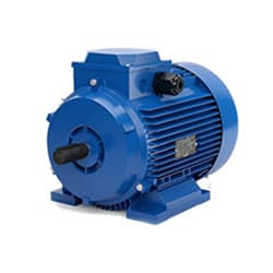 |
| Fig 5: 3 Phase Motor |
A Three-Phase Motor is an Electric Motor That Typically Receives its Power From a Three-Phase System (three-phase current) This can be realized via a Three-Phase Mains Supply or a Frequency Inverter. Three-Phase Motors are Available as Synchronous and Asynchronous Motors. Three Phase Alternating Current Power Motor is Economical to Supply Power to the data Center Since it Requires Less Conductor Material to Supply Electricity. This Explains Why 3 Phase Alternating Current Motor is Used in Electric Transmission, Generation, and Distribution in Most Countries Worldwide.
Thank You for visiting the website. Keep visiting for more Updates.

Post a Comment
Do leave your comments