Photocell Sensor in switch to light wiring:
This diagram shows how to make Photocell Sensor in Switch to Light Wiring. In this circuit, we use an SP MCB ( Single Pole Miniature Circuit Breaker ), a light, an SPST ( Single Pole Single Throw ), and a Day Night sensor. We need to connect all components like our diagram. Now this circuit is ready for use. If you want to know more about this circuit please check our youtube video below the post.
Diagram of photocell sensor wiring:
Components Need for this Project:
You can get the components from any of the sites below:
- Light [See Buy Click Amazon]
- SP MCB [See Buy Click Amazon]
- Switch [See Buy Click Amazon]
- Day-night Sensor [See Buy Click Amazon]
Read Also:
Components used to make the photocell sensor in switch wiring:
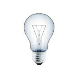
01. Light
 |
| Fig 2: Light |
CFLs work in a completely different way from ordinary lamps, they work by using a different process called fluorescence rather than generating light from heat. A typical light bulb wastes 90% of energy and converts only 10% of energy into light, this is where CFL has the biggest advantage. CFL- Curved or conical glass tube filled with argon and a small amount of mercury vapor. The inner wall of the glass is coated with fluorescent material. CFL- It is manufactured using the principle of creating fluorescent light. CFL- Originally white in color but now the construction and use of CFLs producing colored light has become popular.
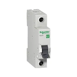
02. SP MCB
 |
| Fig 3: SP MCB |
MCB SP means single pole it protects only one phase switching. MCB (Miniature Circuit Breaker) Curswitch is the most basic general-purpose switch that you use to control a light or another device from one location. These Switches Have Two Brass-Colored Screw Terminals Connected to the hot Power Source Wires. (MCB) For any Distribution Board, the Protection System Must be Used in The Incomer. Phase and Neutral Single Phase Supply to break. 120-volt circuits, 15-20 amp single pole breaker is typically used.
03. Switch
 |
| Fig 4: Switch |
A Single-Pole, Single-Throw (SPST) Switch. It's Got one Output and One Input. The Switch will Either be Closed or Completely Disconnected. SPSTs are Perfect for on-off Switching. They're also a Very Common Form of Momentary Switches. SPST Switches are Commonly Used in a Variety of Electrical Circuits and Applications, Such as Turning on And off Lights, Fans, and Other Appliances. They can Also be Used to Control the Flow of Electricity to Different Parts of a Circuit or to Switch Between Different Circuits Altogether.
04. Day-night Sensor
 |
| Fig 5: Day-night Sensor |
An Automatic Day Night Light Sensor Switch can Switch on Any Electrical Device Automatically When Dark Falls And Switch off in the Morning Automatically. This Night light With an Energy-Efficient LED (Light Emitting Diode) can be Plugged into the Socket and has a light sensor so that the lamp switches on automatically when it gets dark. This is a Photo Technology-Based automatic sensor switch for 220V AC mains, which can be Widely Used in Street Lights, Factories, Gardens, Shops, Etc., and Other Places for Automatic Lighting. Turns ON the Light in the Dark & Turns OFF in The Light.
Thank You for visiting the website. Keep visiting for more Updates.
Frequently Asked Questions
Always connect black wires to black wires and white wires to white wires power supply. Cover all connections with electrical tape and tuck all the current wires away. Finish installing your light fixture per the project system manufacturer's instructions. Once everything is assembled, test your light as Circuit diagram shown above.
Connect the hot wire from your house to the hot wire on the Project system motion sensor. Connect the load wire to your light to the load wire on the Currenttlou motion sensor. Connect the neutral wire from your house to the neutral wire on the Power supply motion sensor.
The power is run to a photocell mounted on the electrical box. The photocell acts as a second switch. If the power supply is on at the first switch, the photocell will control the power supply out of the electrical box.
It is particularly useful for outdoor area lighting. Photocells are variable resistors that adjust the resistance in an electrical circuit diagram based on the level of light present in their mount and location. To function properly, they need to be placed in exposed Project system areas where they can receive sufficient light.
A photocell and photoresistor is a sensor that changes its resistance when light shines on its Circuit diagram. The resistance generated varies depending on the light striking at the surface. A high intensity of light incident on the surface will cause a lower power supply resistance, whereas a lower intensity of light will cause higher Currenttlou resistance.


Post a Comment
Do leave your comments