
Dol starter connection diagram:
This diagram shows how to make a Dol starter connection diagram. Dol motor starter wiring diagram. In this circuit, we use a stop switch, a start switch, an SP MCB ( Single Pole Miniature Circuit Breaker ), a TP MCB ( Tripple Pole Miniature Circuit Breaker ), two indicator lights, a magnetic contactor with overload, 3 phase motor. This circuit is very simple and is very easy to make. If you want to know more about this circuit please stay with our website and check our youtube video below the post.
Diagram of Dol starter wiring:

Components Need for this Project:
You can get the components from any of the sites below:
- 3 Phase Motor [See Buy Click Amazon]
- Contactor [See Buy Click Amazon]
- Overload [See Buy Click Amazon]
- SP MCB [See Buy Click Amazon]
- TP MCB [See Buy Click Amazon]
- Indicator Light [See Buy Click Amazon]
- Stop Switch [See Buy Click Amazon]
- Start Switch [See Buy Click Amazon]
Read Also:
Components used to make the Dol motor wiring:
01. 3 Phase Motor
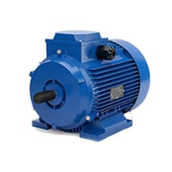 |
| Fig 2: 3-Phase Motor |
A Three-Phase Motor is an Electric Motor That Typically Receives its Power From a Three-Phase System (three-phase current) This can be realized via a Three-Phase Mains Supply or a Frequency Inverter. Three-Phase Motors are Available as Synchronous and Asynchronous Motors. Three Phase Alternating Current Power Motor is Economical to Supply Power to the data Center Since it Requires Less Conductor Material to Supply Electricity. This Explains Why 3 Phase Alternating Current Motor is Used in Electric Transmission, Generation, and Distribution in Most Countries Worldwide.
02. Contactor
 |
| Fig 3: Contactor |
A magnetic contactor is an electrical device used for load control, automation, and protection. It is much like a magnetic reel. However, relays are generally used for low power and voltage, on the other hand, when we think of high power, these heavy-duty contractors only come to mind. It basically works by switching the load on and off. It has 3 terminals whose inputs are denoted as L1, L2, L3, and outputs as T1, T2, and T3. The circuit of the load is made in automation mode or protection using auxiliary contacts. It has two types of terminals. 1) Normally Open (NO). 2) Normally Closed (NC)
03. Overload
 |
| Fig 4: Overload |
Overload relays are often used to protect the motor from excessive current flow. Overload relays are used to protect the motor from overheating. Besides some specific faults such as phase to phase, phase to ground, etc. overload relay provides protection to the motor. A thermal overload relay works on the principle of bimetallic strip electro-thermal characteristics. When the bimetallic heats up, the trip function in the overload relay turns on and disconnects the power supply to the contactor coil, thus tripping the overload relay and breaking the motor current and saving the motor.
04. SP MCB
 |
| Fig 5: SP MCB |
MCB SP means single pole it protects only one phase switching. MCB (Miniature Circuit Breaker) Curswitch is the most basic general-purpose switch that you use to control a light or another device from one location. These Switches Have Two Brass-Colored Screw Terminals Connected to the hot Power Source Wires. (MCB) For any Distribution Board, the Protection System Must be Used in The Incomer. Phase and Neutral Single Phase Supply to break. 120-volt circuits, 15-20 amp single pole breaker is typically used.
05. TP MCB
 |
| Fig 6: TP MCB |
Three wires can be controlled by a triple pole MCB. Triple pole MCB circuit breakers are generally used in three-phase lines. A triple-pole MCB circuit breaker has three wires at its input and three wires at its output. But one can use this circuit breaker in a single-phase line. TP MCB widely used in industries. The reason is that it has three poles. And this TP circuit breaker is used to provide three-phase and three-phase connections. A neutral is not normally used in three-phase lines. But a 4-pole MCB circuit breaker is used if needed.
06. Indicator Light
 |
| Fig 7: Indicator Light |
An electric current Flow Indicator Senses The electrical Current Through an electrical device And produces visible feedback to Indicate Proper Operation. The Current Flow Indicator Has Voltage And Current Regulation Craving First And Second Inputs Connected To The First And Second Conductors, Respectively. This Publication Provides updated Statistics on a Comprehensive Set of social, Economic, Financial, and Environmental Measures as Well as Select Indicators for Sustainable Development Goals.
07. Stop Switch
 |
| Fig 8: Stop Switch |
Indicates the contacts of switches or automatic actionable devices. Simply put, the push switches, magnetic contactors, and relays that we use in the factory Normally have Close Contact exists. At this moment the switch will be in normally closed condition. Because already he is sitting close. When turned off the contact will open. To make ladder logic you need to understand NC contact. As already explained. The switch contact is already closed in NC. That is enough to understand.
08. Start Switch
 |
| Fig 9: Start Switch |
The operator switch has its contact in Normally Open condition. To make Ladder Logic you need to understand NO contact. A Classic Switch has one Input And one Output. In "No Switch," YoungBoy Raps About Ammunition, Murder, Firearms, and Firearm Attachments Such as a Switch. The contact of the switch whose contact is already open is NO. That is enough to understand. no switch in a circuit, then the circuit will not function as intended. to write a program such that when the red light is on, This switch is now in normally open condition. When you push the switch it will close and the red light will turn on.
Thank You for visiting the website. Keep visiting for more Updates.

Post a Comment
Do leave your comments