3 Phase Fuse Board wiring:
This diagram shows how to make 3 phase fuse board wiring or how to wire 3 phase fuse box. In this circuit, we use a TP MCB ( Tripple Pole Miniature Circuit Breaker ), three fuse/cut out, and three indicator lights. First, we need to input the power connection to MCB, then the input connection to all fuse, then the input connection to all lights. Now this circuit is ready for use. if you want to know more about this circuit please stay with us and check our youtube video below the post.
Diagram of wire 3 phase fuse box wiring:
Components Need for this Project:
You can get the components from any of the sites below:
Read Also:
Components used to make the Fuse Board Wiring:
01. TP MCB
 |
| Fig 1: TP MCB |
Three wires can be controlled by a triple pole MCB. Triple pole MCB circuit breakers are generally used in three-phase lines. A triple-pole MCB circuit breaker has three wires at its input and three wires at its output. But one can use this circuit breaker in a single-phase line. TP MCB widely used in industries. The reason is that it has three poles. And this TP circuit breaker is used to provide three-phase and three-phase connections. A neutral is not normally used in three-phase lines. But a 4-pole MCB circuit breaker is used if needed.
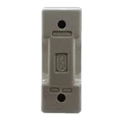
02. Fuse
 |
| Fig 3: Fuse |
A fuse is an electrical, electronic, or mechanical device that protects a circuit from excessive current or overload. The metal of the fuse is made or designed in such a way that it can carry a very small amount of current. When short-circuited or overloaded, the high-flow current generates thermal heat that melts the fuse's metal or element and creates a gap. This gap interrupts the flow of current in the fuse. Basically, this is how a fuse works. If the fuse is once blown or damaged it needs to be replaced to allow current to flow again in the circuit.
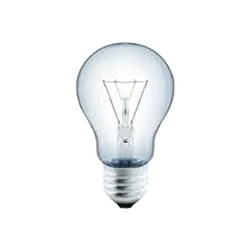
03. Indicator Bulbs
 |
| Fig 4: Indicator Bulbs |
An electric current Flow Indicator Senses The electrical Current Through an electrical device And produces visible feedback to Indicate Proper Operation. The Current Flow Indicator Has Voltage And Current Regulation Craving First And Second Inputs Connected To The First And Second Conductors, Respectively. This Publication Provides updated Statistics on a Comprehensive Set of social, Economic, Financial, and Environmental Measures as Well as Select Indicators for Sustainable Development Goals.
Thank You for visiting the website. Keep visiting for more Updates.


Post a Comment
Do leave your comments