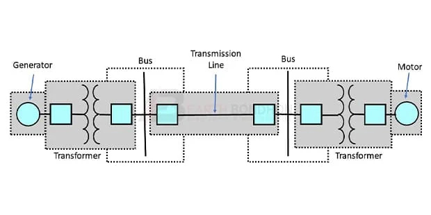
Power System of Single Line diagram:
This diagram shows how to connect Single line diagram is also called as blueprint of electrical system analysis. With the help of this single line diagram substation can be designed very easily. Below are some symbols of single line diagram. In addition to these symbols, single line diagrams can also use numerous symbols. So you can wire your house or office like this diagram very easily. If you want to learn how to connect this circuit clearly you can follow our youtube video link in below.
Diagram of Power System of Single Line diagram:
Components Need for this Project:
You can get the components from any of the sites below:
- Generator [See Buy Click Amazon]
- Transformer [See Buy Click Amazon]
- Busbar [See Buy Click Amazon]
- Motor [See Buy Click Amazon]
*Please note: These are affiliate links. I may make a commission if you buy the components through these links. I would appreciate your support in this way!
Read Also:
Components used to make the Power System of Single Line diagram:
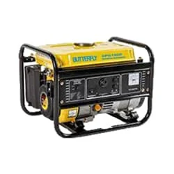
01. Generator
 |
| Fig 2: Generator |
The Power Generator Is a Device That Converts Motive Power (Mechanical Energy) or Fuel-Based Power (Chemical Energy) Into Electric Power for Use in an External Circuit. In Addition to Electromechanical Designs, Photo Voltaic, And Fuel Cell-Powered Generators Utilize Solar Power and Hydrogen-Based Fuels, Respectively, to Generate Electrical Output. The Reverse Conversion of Electrical Energy Into Mechanical Energy is Done by an Electric Motor, And Motors, And Generators Have Many Similarities. Many Motors can be Mechanically Driven to Generate Electricity; Frequently They Make Acceptable Manual Generators.
02.Transformer
 |
| Fig 3: Transformer |
Three-phase Transformers are Passive Machines That Pass Electric Energy Between Circuits. In the Secondary Circuit, a Magnetic flux Induces an Electromotive Force (emf), Thus Stepping up (increasing) or Stepping down (decreasing) Voltages Without Altering the Frequency. There are Different Kinds of Electrical Systems and Therefore Transformers have to Operate Alongside Compatible Systems. A 3-phase Transformer Works with 3 Phase AC Electrical System to Provide Consumers With Stable and Device-Safe Electricity.
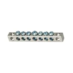
03. Busbar
 |
| Fig 4: Busbar |
Busbar is a type of power transmission sheet. It is made of copper or brass or aluminum. Busbar is mostly used in factories. We supply the power from the transformer to the busbar. Busbars have electricity. We take the electricity from this busbar to the circuit breaker. The busbar is drilled with a drill machine and the cable is connected with a nut bolt. The advantage of using a busbar is that through it we can provide multiple power connections in multiple places very easily.
04. Motor
 |
| Fig 5: Motor |
A Three-Phase Motor is an Electric Motor That Typically Receives its Power From a Three-Phase System (three-phase current) This can be realized via a Three-Phase Mains Supply or a Frequency Inverter. Three-Phase Motors are Available as Synchronous and Asynchronous Motors. Three Phase Alternating Current Power Motor is Economical to Supply Power to the data Center Since it Requires Less Conductor Material to Supply Electricity. This Explains Why 3 Phase Alternating Current Motor is Used in Electric Transmission, Generation, and Distribution in Most Countries Worldwide.
Thank You for visiting the website. Keep visiting for more Updates


Post a Comment
Do leave your comments