Electrical Switch Board Wiring Diagram | Switchboard diagram
Electrical Switch Board Wiring Diagram:
This diagram shows how to connect the electrical switchboard wiring diagram. In this video, we just try to describe to you how to connect switchboard wiring very easily. In this circuit, we use a 5-pin power socket, 3 switches, a fan regulator, a light, and a ceiling fan. If you want to know more details about this circuit please follow our youtube video at the below link.
Digram of Switch Board Wiring:
Components Need for this Project:
You can get the components from any of the sites below:
- 5-Pin Socket [See Buy Click Amazon]
- Fan Regulator [See Buy Click Amazon]
- Ceiling Fan [See Buy Click Amazon]
- Light [See Buy Click Amazon]
*Please note: These are affiliate links. I may make a commission if you buy the components through these links. I would appreciate your support in this way!
$ads={1}Read Also:
Components used to make the Switch Board Wiring:
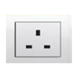
01. 5-Pin Socket
 |
| Fig 2: 5-Pin Socket |
A socket is a type of equipment used in electrical wiring lines that always has an electrical connection. According to the need, it can be supplied to the electrical equipment. In case of electric iron, electric hand drill machine and electric hand grinder etc. two-pin socket with earth terminal is used. Also, three-pin sockets are used for electrical appliances that have a metal body and are likely to be electrified. Eg – Refrigerator, room heater, table heater, hot-plate, electric oven etc.
02. Fan Regulator
 |
| Fig 3: Fan Regulator |
Reduces fan speed by switching on and off. Reducing the speed of the fan, the power Consumption is also Reduced. It is basically a wire wood resistor-based regulator. The large regulators that were used in the past took up more than half of the switchboard space and were very hot. It looks very small in size. Almost equal to a switch. Electrical regulators are basically made by winding copper wire on an iron core. As Electricity Travels Long Distances Through These Wires, Some of The Electrical Energy is Converted Into Heat Energy.
03. Ceiling Fan
 |
| Fig 4: Ceiling Fan |
The main driving force behind all ceiling fan systems is the motor used inside the fan. We can also compare it with the soul of a fan. This motor converts the supplied electrical energy into mechanical energy which turns the ceiling fan and gives us air. When current is supplied, the magnetic field formed on the positive half-cycle becomes the reverse magnetic field on the next negative half-cycle. The magnitude part does not rotate and the capacitor is converted to a phase when it is connected to a phase motor or ceiling fan with a helical coil or stationing coil. When power is supplied there is a magnetic difference between the phase currents and the coils (acting as two phases) so that the motor or fan rotates.
04. Light
 |
| Fig 5: Light |
CFLs work in a completely different way from ordinary lamps, they work by using a different process called fluorescence rather than generating light from heat. A typical light bulb wastes 90% of energy and converts only 10% of energy into light, this is where CFL has the biggest advantage. CFL- Curved or conical glass tube filled with argon and a small amount of mercury vapor. The inner wall of the glass is coated with fluorescent material. CFL- It is manufactured using the principle of creating fluorescent light. CFL- Originally white in color but now the construction and use of CFLs producing colored light has become popular.
Thank You for visiting the website. Keep visiting for more Updates.
$ads={2}
Frequently Asked Questions
What are the basics of an electrical switch?
The low-resistance metal contacts make or break the electrical circuit diagram. A switch is an electromechanical device that completes or breaks a current flow path within a circuit or sends current over a different path. Despite the many switches of the types, they have basic components in common.
What is basic electrical wiring?
Electrical wiring is an electrical installation of cabling or associated devices such as switches, distribution boards, sockets, or light fittings in a structure. Electrical of the symbols for wiring. Wiring is subject to safety standards for design or installation.
What is a 4-way switch?
A single-pole switch has two terminals or controls one light fixture from one location. A 3-way switch has three terminals and can control a fixture from two locations. Like these, a 4-way device has a ground terminal but can control one fixture from at least three different locations.
How do 4-way switches work?
A four-way switch has four terminals that provide two sets of toggle of the positions. When the switch is in the up position, the current can flow through two terminals. In the down of the position, the current flows through the other 2 terminals.
What is a switch in a circuit diagram?
In electrical engineering a switch is an electrical component that can disconnect and connect the conducting path in an electrical circuit diagram, interrupting the electric current and diverting it from one conductor to another.


Post a Comment
Do leave your comments